Repair Chevrolet Repair Toyota Repair Honda Repair AvtoVAZ Repair Mercedes-Benz Repair BMW Repair Opel
Home  |  Contacts  |  Sitemap  |    
English Русский
Български
Беларускі
Український
Српски
Hrvatski
Română
Polski
Slovenský
Magyar
AudiManual.ru


  • AUDI 80
  • AUDI 100
  • AUDI A3
  • AUDI A4
  • AUDI A6
  • AUDI A8
  • AUDI Q
  • OTHER
  • ARTICLES
B8 (2007-2015) B7 (2004-2008) B6 (2000-2006) B6 (2000-2006, petrol) B5 (1994-2001) B5 (1994-2001, petrol)

Dismantling a petrol pump with an electric drive (Audi A4 B5)

  • Home
  • Audi A4
  • B5 (1994-2001, petrol)
  • Power unit
  • Fuel system
  • Dismantling a petrol pump with an electric drive
            0
The so-called fuel supply module consists of:

The so-called fuel supply module consists of:

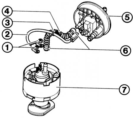
  • 1 - mounting nuts for connecting the pump to the power supply;
  • 2 - electrical wires from the blind flange to the fuel pump;
  • 3 - clamps for wires/hose;
  • 4 - fuel hose;
  • 5 - blind flange;
  • 6 - clamping clamps;
  • 7 - support body with fuel pump.

7 - support body with fuel pump.


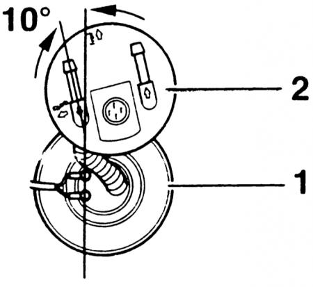
Quattro: The hose between the fuel pump (1) and the blind flange (2) must be installed as shown in the figure.

Quattro: The hose between the fuel pump (1) and the blind flange (2) must be installed as shown in…


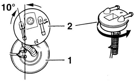
Front wheel drive: The illustration shows how to install the hose between the fuel pump (1) and the blind flange (2). When installing, turn the blind flange in the direction of the arrow as shown on the right.


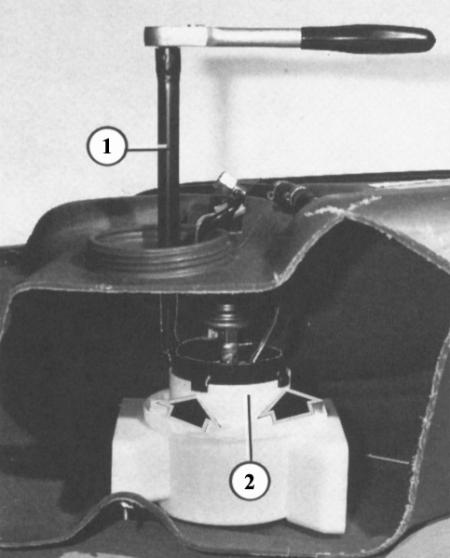
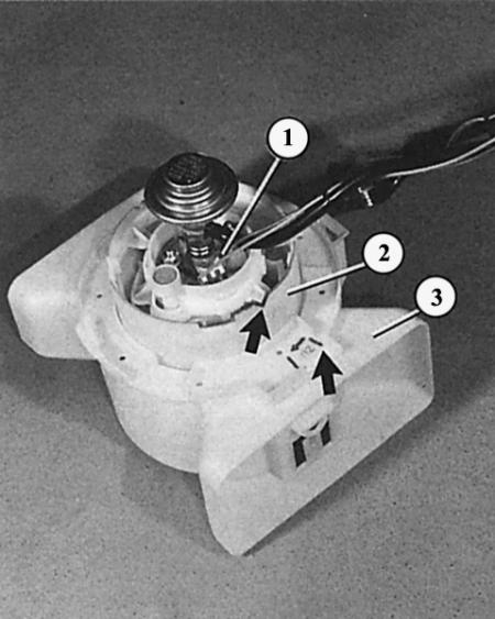
This cut fuel tank shows how to remove the fuel pump. Although this requires a special tool (1), which turns the inner part (2) of the intake manifold housing slightly to the left. The tool catches the recesses of the inner part with its claws (arrows).

This cut fuel tank shows how to remove the fuel pump. Although this requires a special tool (1),…


To install the fuel pump (1) with the inner part (2) of the intake manifold housing into the outer part (3) of its housing, the installation position must be correct: the mark on the inner part of the intake manifold housing must be opposite the mark on the outer part (arrows).

To install the fuel pump (1) with the inner part (2) of the intake manifold housing into the outer…


This is a job for an Audi workshop, as the fuel pump is removed together with the inner part of the intake manifold housing and can only be unscrewed from the outer part of the intake manifold with a special key 3307. Anyone who can borrow the key should proceed as follows:


Execution order


1. Make sure the fuel tank is filled to a maximum of 2/3, otherwise the petrol will leak out!

2. Fold back the boot floor covering.

3. Unscrew the black cap.

4. Disconnect the multi-pin connector.

5. Disconnect the recirculation pipe.

6. Disconnect the supply line.

7. Unscrew the synthetic union nut. Most often, they sit very tightly. Therefore, place the bluntest screwdriver on the edge of the nut, and lightly tap the handle of the screwdriver with a hammer to loosen the nut. If necessary, tap on different edges.

8. Now you can pull the blind flange of the fuel tank up a little.

9. Loosen the recirculation pipe clamp on the inside of the blind flange and pull the hose down.

10. Remove the fuel tank connector.

11. Install special key 3307 on the inner part of the intake manifold housing.

12. Turn the inner part of the intake manifold housing slightly to the left until it stops.

13. Remove the pump with the inner part and together with the blind flange from the fuel tank.

14. Mark/remember the installation position of the pump, hoses, wires and wire harnesses, as the parts must be installed accurately during installation.

15. After unscrewing the discharge pipeline (mounting position) the pump can be removed from the inner part of the intake manifold housing. This is done differently depending on the pump version:

16. 60mm pump: turn the sieve under the inner part of the intake manifold housing to the left, take out the pump. When installing, the spout on the side of the pump should be pushed into the groove. Pay attention to the gasket.


17. 40mm pump: Press the release clamp at the top of the inner part of the intake manifold housing, remove the pump. When installing, the pump can only be inserted in one position.

18. Installation: Install the hose between the pump and the blind flange as shown in the figures. The pump and the blind flange must be in the correct position relative to each other.

19. If everything is assembled correctly, the pump can be reinstalled into the outer part of the intake manifold housing in the fuel tank.

20. Please note: the mark on the outer part must be opposite the mark on the inner part.

21. Tighten the inner part again with key 3307, install the remaining parts.

22. Installation position of the blind flange: the arrow on the flange must be opposite the mark on the fuel tank. Front-wheel drive and all-wheel drive vehicles have their own arrow.

The original text of the material can be found on the website AudiManual.ru
The article was checked by auto expert Georgy Rodionov
This article is available at russian, bulgarian, belarusian, ukrainian, serbian, croatian, romanian, polish, slovak, hungarian

Share information:
Previous articles
Audi A4 B5: Fuel system
Next articles

Electric fuel pump
Dismantling fuel lines
Fuel tank fuel level indicator sensor
What is fuel tank ventilation for?
Replacing the fuel filter
Removal the air filter insert
Blowing out the air filter insert
Preheating of intake air


Similar articles on other Audi car models:
Electric water pump for TD diesel engines Audi 80 B4 (1991-1996)
Electric seat adjustment drive Audi 100 C3 (1982-1990, diesel)
Electric windows and rear view mirrors Audi A3 Type 8L (1996-2003)
Checking the injection pump drive belt (2.5L engine) Audi A6 C4 (1994-1997)
Oil pan and oil pump for 2.8L petrol engine Audi A8 D2 (1994-2002)
Removal and installation the fuel injection pump drive belt Audi Q7 Typ 4L (2005-2015, diesel)
Timing Belt (4-cyl. petrol engine) Audi A2 (1999-2005)
Link to this page in different formats


Visitor comments

No comments yet


How much will 46 + 12 =


A4(B8, 2007-2015) 
  • General information
  • Operating instructions
  • Power unit
  • Petrol engines 1.8 l
  • Petrol engines 1.8/2.0 l
  • Petrol engines 3.0 l
  • Petrol engines 3.2 l
  • Fuel system (petrol)
  • Diesel engines 2.0 l (CA*)
  • Diesel engines 2.0 l (CJCB)
  • Diesel engines 2.7/3.0 l
  • Diesel engines 3.0 l
  • Fuel system (diesel)
  • Transmission
  • Manual gearbox 0B1
  • Manual gearbox 0B2
  • Manual gearbox 0B3
  • Manual gearbox 0B4
  • Automatic transmission 0B5
  • Automatic transmission 0B6
  • Automatic transmission 0AW
  • All-wheel drive system
  • Chassis
  • Front suspension
  • Rear suspension
  • Brake system
  • Steering system
  • Body
  • Exterior
  • Interior
  • Seats
  • Doors, locks and windows
  • Security system
  • Heating and air conditioning
  • Electrical equipment
  • Audio system
  • Power devices
  • Equipment and devices
  • Lighting and lamps
  • Electrical circuits
 
A4(B7, 2004-2008) 
  • General information
  • Introduction to manual
  • Troubleshooting
  • Operating instructions
  • Maintenance
  • Power unit
  • Petrol engines 2.0 (ALT)
  • Petrol engines 2.0 (TFSI)
  • Petrol engines 1.8 (MPI)
  • Diesel engines
  • Cooling system
  • Air conditioner
  • Fuel and exhaust system
  • Ignition system
  • Starting and charging
  • Transmission
  • Clutch
  • Manual gearbox
  • Automatic gearbox
  • Drive shafts
  • Chassis
  • Brake system
  • Front suspension
  • Rear suspension
  • Steering
  • Body
  • Exterior
  • Interior
  • Electrical equipment
  • Equipment and devices
  • Lighting and signaling
  • Windscreen wipers and washers
  • Electrical diagrams
  • Electrical diagrams (since 2007)
 
A4(B6, 2000-2006) 
  • General information
  • Vehicle Description
  • User manual
  • Maintenance
  • Power unit
  • Gasoline engine
  • Diesel engine
  • Lubrication system
  • Cooling system
  • Supply system
  • Injection system
  • Exhaust system
  • Ignition and control
  • Transmission
  • Gear box
  • Clutch and drive shafts
  • Chassis
  • Brake system
  • Car suspension
  • Steering
  • Body
  • Heating and ventilation
  • Exterior (external elements)
  • Interior (internal elements)
  • Electrical equipment
  • Power devices
  • Lighting and appliances
  • Electrical circuits
 
A4(B6, 2000-2006, petrol) 
  • General information
  • Introduction to the guide
  • Car care
  • Power unit
  • Engine repair
  • Lubrication system
  • Cooling system
  • Injection and control system
  • Ignition system
  • Power and exhaust system
  • Transmission
  • Clutch and drive shafts
  • Car gearbox
  • Chassis
  • Suspension and wheels
  • Steering
  • Brake system
  • Body
  • Interior
  • Exterior
  • Electrical equipment
  • Equipment and devices
  • Lighting and signaling
  • Power devices
  • Electrical circuits
 
A4(B5, 1994-2001) 
  • General information
  • Introduction to the guide
  • Car care
  • Maintenance (gasoline)
  • Maintenance (diesel)
  • Power unit
  • Gasoline engines
  • Diesel engines
  • Engine overhaul
  • Cooling system
  • Fuel injection (gasoline)
  • Fuel system (diesel)
  • Exhaust system
  • Ignition system
  • Transmission
  • Clutch
  • Mechanical gearbox
  • Automatic gearbox
  • Drive shafts
  • Chassis
  • Brake system
  • Car suspension
  • Steering
  • Body
  • Exterior
  • Interior
  • Doors, locks and windows
  • Heating and ventilation
  • Electrical equipment
  • Power devices
  • Equipment and devices
  • Electrical circuits
 
A4(B5, 1994-2001, petrol) 
  • General information
  • Vehicle description
  • Maintenance
  • Power unit
  • Engine repair
  • Turbocharging
  • Exhaust system
  • Cooling system
  • Ignition system
  • Fuel system
  • Motronic injection system
  • MPI and MPFI injection system
  • Transmission
  • Clutch
  • Gearbox and shafts
  • Chassis
  • Steering
  • Car suspension
  • Brake system
  • Wheels and tires
  • Body
  • Heating and ventilation
  • Body parts
  • Electrical equipment
  • Fuses and relays
  • Power devices
  • Lighting and lamps
  • Tools and devices
  • Electrical circuits
 
AudiManual.ru © 2017-2026 · Mobile version · Feedback · Sitemap: EN BG BY UA RS HR RO PL SK HU · Site search · News and articles
80 B2 · 80 B3 petrol · 80 B3 · 80 B4 · 100 C3 diesel · 100 C3 petrol · 100 C3 · 100 C4 petrol · 100 C4 · A3 Type 8L · A4 B5 petrol · A4 B5 · A4 B6 petrol · A4 B6 · A4 B7 · A4 B8 · A6 C4 · A6 C5 · A6 C5 Allroad · A8 D2 · Q5 Type 8R · Q7 Typ 4L · Audi A2 ·
This site uses cookies 🍪. Click the button to accept this fact.