
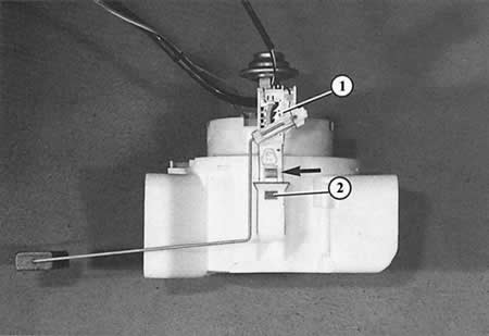
The support body photographed here is usually glued into the fuel tank; but here it is shown separately for the sake of clarity. Dismantling of the fuel level sensor (1) is possible after pressing the key (arrow). The pressed key removes the lock (2). The fuel level sensor can be removed.
Here you can see the blind flange of the fuel tank under the bottom of the trunk.
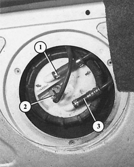
The numbers indicate:
- 1 - return fuel line from the injection system;
- 2 - connector for connecting the fuel pump and fuel level sensor;
- 3 - fuel supply line to the injection system.
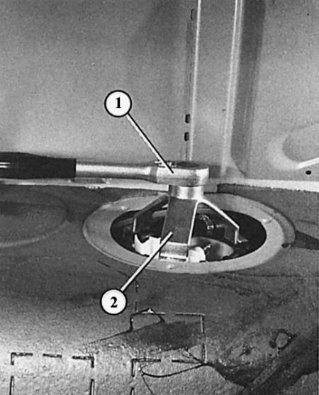
The fuel level sensor locking ring is unscrewed here with a special tool (2) using a ratchet (1).
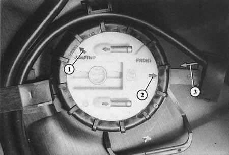
Mounting position of the blind flange: the arrow on the flange (1 or 2) must be opposite the mark on the fuel tank (3). In vehicles with front-wheel drive and all-wheel drive, there is a corresponding arrow in each case.
The sensor is inserted into the intake manifold housing on top, inside the middle of the fuel tank. How it works, you will find in the chapter Tools and instruments.
Due to the different shape of the fuel tanks, there are also different fuel level sensors for front-wheel drive and all-wheel drive models. Identification feature: fuel level sensor with rectangular float for front-wheel drive models; fuel level sensor for quattro – with ball float.
Removal the fuel level sensor
Important: the fuel tank can be filled to a maximum of 2/3, otherwise the fuel will leak out!
1. Fold back the boot floor covering.
2. Unscrew the black metal cap.
3. Mark the fuel supply and return lines - arrows on the fuel line nozzles show the direction of flow.
4. Remove both fuel lines after opening the clamps.
5. Unscrew the plastic union nuts. Most often they are very tightly seated. Therefore, if possible, place a blunt screwdriver on the edge of the nut and loosen the nut with light blows of a hammer on the screwdriver handle. If necessary, install it on different edges of the nut.
6. Now you can pull the blind flange of the fuel tank up a little.
7. If necessary, remove the return fuel line and electrical wire from the back of the blind flange.
8. Mark the mounting position of the hose and wire for subsequent assembly.
9. Now grab the fuel tank with your hand and remove the sensor while simultaneously pushing the mounting tab out of the intake manifold housing.
10. Disconnect the fuel level sensor connector on the blind flange.
11. Before assembly, moisten the sealing ring of the blind flange with gasoline.
12. Installation position of the blind flange: the arrow on the flange must be opposite the mark on the fuel tank. Front-wheel drive and all-wheel drive vehicles have their own arrow for each case.
Text provided by the online resource audimanual.ru