
Repair Chevrolet Repair Toyota Repair Honda Repair AvtoVAZ Repair Mercedes-Benz Repair BMW Repair Opel
Home  |  Contacts  |  Sitemap  |    
English Русский
Български
Беларускі
Український
Српски
Hrvatski
Română
Polski
Slovenský
Magyar
AudiManual.ru


  • AUDI 80
  • AUDI 100
  • AUDI A3
  • AUDI A4
  • AUDI A6
  • AUDI A8
  • AUDI Q
  • OTHER
  • ARTICLES
B4 (1991-1996) B3 (1986-1991) B3 (1986-1991, petrol) B2 (1979-1986)

Intake manifold with variable internal cavity configuration (Audi 80 B4)

  • Home
  • Audi 80
  • B4 (1991-1996)
  • Power unit
  • Fuel system
  • Intake manifold with variable internal cavity configuration
            0
Table of contents: 2.8L six-cylinder engine ↓ Removal ↓ Installation ↓

2.8L six-cylinder engine


High engine torque even at low revs is provided by a long intake manifold with small diameter pipes. To ensure high engine power at high revs, on the contrary, a short intake manifold with large diameter pipes is required.

To combine these two approaches, AUDI has developed an intake manifold with a variable configuration of the internal cavity. In the pipes of this intake manifold there are six flaps that close and open depending on the engine load. Thus, each cylinder has an intake pipe of different length and diameter, which can be designated as an intake pipe for maintaining high torque and an intake pipe for developing the engine's power characteristics. The flaps in the intake manifold pipes are actuated by low-pressure air depending on the engine speed. Up to 4,000 rpm, they are in a closed position, providing the engine with high torque. At engine speeds exceeding 4,000 rpm, the flaps are fully open.

If the engine's effective power drops, it is necessary to check the operation of the flaps in the intake manifold pipes.

1. First check the ease of movement of the damper rod.

2. Check the functionality of the flaps. This check is performed with the engine warmed up.

3. Start the engine and increase its speed to over 4000 rpm.

4. Watch the diaphragm valve of the intake manifold flaps. The throttle linkage should move back. If this does not happen, check the condition of the low-pressure air hoses and make sure that they are tight. If so, then:


5. Check the diaphragm valve. To do this, attach a spare low-pressure air hose to the valve connection pipe and suck air from the hose with your mouth. If the intake manifold flaps drive rod does not move or there is always air in the hose despite attempts to pump it out with your mouth, then the diaphragm valve is faulty and must be replaced. If the diaphragm valve is normal, then check the sequential intake manifold sequential valve. This valve is located next to the air mass flow meter at the rear of the engine on the right side. This valve determines the need to supply low air pressure to the diaphragm valve (see illustration).
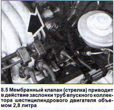
5. Check the diaphragm valve. To do this, attach a spare low-pressure air hose to the valve…


6. Disconnect the two low pressure air hoses from the intake manifold sequential valve (see illustration). Attach a spare low pressure air hose to the valve outlet that leads to the intake manifold.
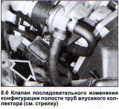
6. Disconnect the two low pressure air hoses from the intake manifold sequential valve (see…


7. Draw air from this hose with your mouth. No air should pass through the hose.


8. Start the engine and increase the speed to 4000 rpm or higher.

9. Suck air from the hose with your mouth. Air should now pass through the hose. If the defect cannot be identified, which is unlikely, then contact the workshop.

Removal


10. Remove the protective cover over the engine.

11. Remove the spark plug caps and release the high tension wires from the holders.

12. Disconnect the fuel distribution line together with the injectors.

13. Disconnect the air intake hose.

14. Remove the idle speed control valve or disconnect its connector.

15. Disconnect all low-pressure hoses from the intake manifold. Also remove the hose from the throttle body and the crankcase ventilation hose.

16. Disconnect the gas cable and the throttle position potentiometer plug.

17. Unscrew the intake manifold mounting bolts. The sequence of unscrewing the bolts is the opposite of their tightening (see illustration).
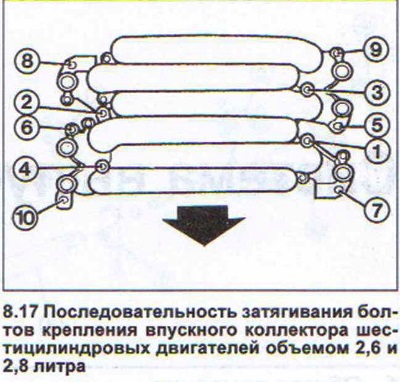
17. Unscrew the intake manifold mounting bolts. The sequence of unscrewing the bolts is the…


18. Remove the intake manifold together with the throttle body pipe.

Installation


19. Replace the old gaskets with new ones.

20. Tighten the intake manifold mounting bolts in the sequence shown in Illustration 8.17. Tighten the bolts in four passes to the following torques:


1st stage: 5 Nm;
2nd stage: 10 Nm;
stage 3: 20 Nm;
stage 4: 20 Nm.

Attention! Dismantling and installation of the intake manifold of a six-cylinder engine with a volume of 2.6 liters are performed identically. The moments and tightening order of the manifold mounting bolts are the same as for a 2.8 liter engine.
The article was checked by auto expert Timur Bazhenov
This article is available at russian, bulgarian, belarusian, ukrainian, serbian, croatian, romanian, polish, slovak, hungarian

Share information:
Previous articles
Audi 80 B4: Fuel system
Next articles

Intake manifold — heating
Intake air heating
Air filter (petrol models) — removal, cleaning, replacement
Fuel filter
Diesel engines — fuel heating


Similar articles on other Audi car models:
Variable length intake manifold Audi 100 C4 (1990-1994, petrol)
Switchable intake manifold Audi A4 B5 (1994-2001, petrol)
Intake manifold Audi A6 C4 (1994-1997)
Intake manifold Audi A8 D2 (1994-2002)
Upper part of the intake manifold Audi Q5 Type 8R (2008-2017)
Intake camshaft gear with variable valve timing Audi A2 (1999-2005)
Link to this page in different formats


Visitor comments

No comments yet


How much will 32 + 48 =


80(B4, 1991-1996) 
  • General information
  • User manual
  • Maintenance
  • Troubleshooting
  • Power unit
  • Engine
  • Cooling system
  • Heating and ventilation
  • Petrol injection
  • Diesel fuel system
  • Fuel system
  • Exhaust systems
  • Ignition system
  • Transmission
  • Clutch
  • Car gearbox
  • Chassis
  • Brake system
  • Suspension and steering wheel
  • Body
  • Body and trim
  • Electrical equipment
  • Electrical system
  • Electrical circuits
 
80(B3, 1986-1991) 
  • General information
  • Repair characteristics
  • Maintenance
  • Power unit
  • Gasoline engine
  • Diesel engine
  • Engine lubrication system
  • Fuel system (gasoline)
  • Injection system (gasoline)
  • Fuel system (diesel)
  • Ignition system
  • Cooling system
  • Heater
  • Exhaust system
  • Transmission
  • Clutch and gearbox
  • Chassis
  • Steering
  • Brake system
  • Car suspension
  • Body
  • Body elements
  • Electrical equipment
  • Power devices
  • Lighting and appliances
  • Electrical circuits
 
80(B3, 1986-1991, petrol) 
  • General information
  • User manual
  • Maintenance
  • Power unit
  • Engine 4-cylinder
  • Engine 5-cylinder
  • Cooling system
  • Fuel and exhaust systems
  • Ignition system
  • Transmission
  • Clutch
  • Mechanical transmission
  • Automatic transmission
  • Drive shafts
  • Chassis
  • Brake system
  • Suspension
  • Steering
  • Body
  • Exterior
  • Interior
  • Electrical equipment
  • Equipment and devices
  • Electrical circuits
 
80(B2, 1979-1986) 
  • General information
  • User manual
  • Power unit
  • Engine FZ
  • Engine EP, YP, YZ, DT, DS, DZ
  • Transmission
  • Clutch
  • 4 speed gearbox
  • 5 speed gearbox
  • Front wheel drive
  • Chassis
  • Front suspension
  • Rear suspension
  • Steering
  • Brake system
  • Electrical equipment
  • Equipment and devices
  • Electrical circuits
 
AudiManual.ru © 2017-2026 · Mobile version · Feedback · Sitemap: EN BG BY UA RS HR RO PL SK HU · Site search · News and articles
80 B2 · 80 B3 petrol · 80 B3 · 80 B4 · 100 C3 diesel · 100 C3 petrol · 100 C3 · 100 C4 petrol · 100 C4 · A3 Type 8L · A4 B5 petrol · A4 B5 · A4 B6 petrol · A4 B6 · A4 B7 · A4 B8 · A6 C4 · A6 C5 · A6 C5 Allroad · A8 D2 · Q5 Type 8R · Q7 Typ 4L · Audi A2 ·
This site uses cookies 🍪. Click the button to accept this fact.