



Table of contents: Examination ↓ Removal ↓
In AUDI 80 cars with petrol engines, the electric fuel pump is located in the lower housing, which in turn is mounted in the fuel tank. The fuel pump receives power through the fuel pump relay and only when the engine is running. The battery switch is included in the fuel pump power supply circuit, preventing fuel ignition in the event of an accident.
Examination
1. Check the fuses. If they are OK, check if the fuel pump operates when the engine is started.
2. Ask an assistant to turn on the ignition. Listen to see if the fuel pump is running. If you hear the noise of the fuel pump running, check if it is delivering fuel.
3. Four-cylinder engines with Mono-Motronic fuel injection. Disconnect the fuel supply line at the junction with the high-pressure fuel lines of the injectors.
4. Place a hose on the released end of the fuel supply line and lower it into the container.
5. Ask an assistant to operate the starter. Fuel should flow through the system.
6. Four-cylinder engines with Digifant injection system. Disconnect the fuel supply line from the fuel rail.
7. Place a hose on the released end of the fuel supply line and lower it into the container.
8. Ask an assistant to operate the starter. Fuel should flow through the system.
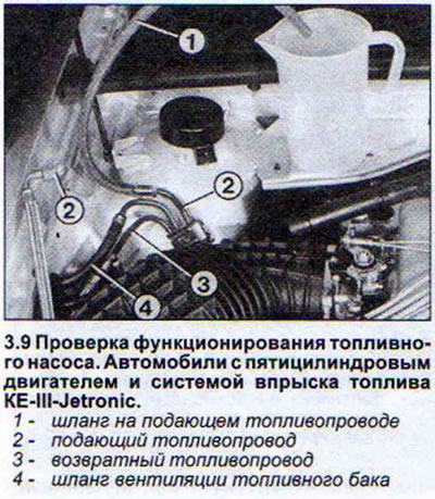
9. Five-cylinder engines with KE-III-Jetronic fuel injection system. Disconnect the fuel supply line. Have a rag ready in case of fuel leakage. Fuel should flow out even when the engine is off, because the pressure in the system is maintained by the operation of the hydraulic accumulator. If fuel does not flow out, ask an assistant to start the starter (see illustration).
10. Six-cylinder engine with MP1/MPFI fuel injection system. Disconnect the fuel supply line from the distribution line and also put a hose on the fuel supply line, the free end of which should be lowered into a container.
11 All engines: Check the multi-plug on the fuel pump connection flange and ensure that power is supplied to the fuel pump motor by removing the boot floor covering and unscrewing the bolts securing the black cover to the underbody.
12. Disconnect the multi-pin plug.
13. Connect a voltmeter or tester with a control diode lamp to the plug contacts 1 and 4 (brown and green-yellow wires) and make sure that 12 V power is supplied to the electric motor. To check the voltage, have an assistant crank the starter. The gearshift lever should be in neutral and the parking brake should be applied. If the power to the pump is normal and it does not work, then the pump is faulty and must be replaced. If there is no power, then it is necessary to check the fuel pump relay on the central distribution panel. Other reasons for the failure of the fuel pump may be:
- break in power supply wire to relay or fuel pump;
- clogged or kinked fuel line;
- clogged filter or hydraulic accumulator.
Removal
The fuel pump must be removed by a workshop because the pump is removed together with the inner component of the lower casing. The fuel pump is disconnected from the lower casing using a special key 3307. If the specified key is available, then to remove the fuel pump, perform the following steps.
1. Disconnect the multi-pin plug.
2. Squeeze the leashes of the fuel return line connecting clamps and disconnect it (see illustration 2.4).
3. Disconnect the supply hose.
4. Unscrew the plastic union nut. Usually this nut is tightened tightly and unscrews with difficulty. In such cases, it is recommended to place a screwdriver on the edge of the nut and, hitting the screwdriver handle with a hammer, loosen the nut.
5. Remove the fuel tank connecting flange by pulling it upwards. If necessary, disconnect the fuel return line connecting pipe from the back of the flange by squeezing its leashes.
6. Disconnect the fuel gauge sensor connector.
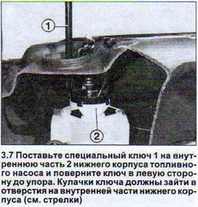
7. Place the special key 3307 on the inside of the lower housing of the fuel pump and turn the key to the left until it stops (see illustration).
8. Remove the fuel pump together with the inner part of the lower housing and the connecting flange.
9. Mark the installation positions of the fuel pump, hoses, power wires and wire attachment points so that you can later install them in their original locations.
10. Mark the installation position of the fuel pressure line.
11. Disconnect the fuel pressure line and remove the pump from the inside of the lower housing. Depending on the type of fuel pump, this procedure is performed differently.
12. Fuel pump 60 mm. Turn the sieve at the bottom of the inner part to the left and remove the pump. When installing, the protrusion on the pump body should go into the groove of the inner part of the lower body. Do not forget to install the sealing ring. 1
13. Fuel pump 40 mm. Press together the retaining clips on the inside of the lower housing and remove the pump. Subsequent installation of the pump is possible only in one position.
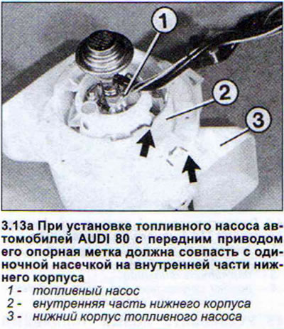
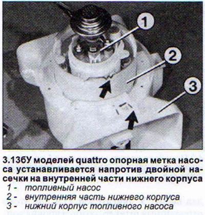
Attention! When installing the fuel pump of AUDI 80 cars with front-wheel drive, its reference mark must coincide with a single notch on the inside of the lower housing. For quattro models, the pump reference mark is installed opposite the double notch on the inside of the lower housing (see illustrations).
14. Screw the inner part into the lower housing using key 3307 and connect all the removed elements.
Attention! When installing the connecting flange, the arrow on the flange must be positioned opposite the mark on the fuel tank.