



Table of contents: Switching relays - testing ↓ Ignition switch X-contact unloading… ↓
All the wires in AUDI 80 cars are combined into bundles that are connected to the central distribution panel - a waterproof black box in the rear left part of the engine compartment. This box contains 21 fuses (diesel vehicles have 22 fuses), 10 additional fuses, 4 spare fuses and 11 relays. In addition, the diagnostic connector is located here.
If the fault finding reveals that the wires are OK, as are the corresponding fuse and relay, the central distribution panel may be the cause of the defect. Typical defects are loose contacts or failures caused by temperature changes. In such cases, the central distribution panel must be replaced.
1. Purchase a new distribution panel. Make sure that the panel you purchase fully complies with the one installed on your vehicle.
2. Open the panel cover and detach the hinges.
3. Press down on the brackets holding the panel and remove it along with the connected wires.
4. Disconnect all the plugs in order from the old distribution panel and connect them to the new one.
5. Install the new panel into the mounting frame.
6. Make sure all wires are connected.
Caution! The cover of the central distribution panel must be closed. Otherwise, a draft will be felt in the footwell on the driver's side when driving.
All other relays are located on an additional block located under the instrument panel on the left side. Access to this block is blocked by the panel overlay (see illustrations 2.0a, 2.0b, 2.0c).
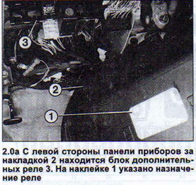
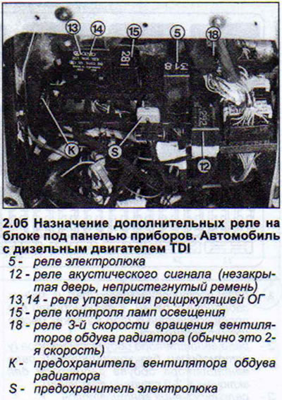
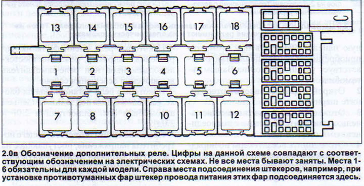
Conventional switching relays are installed for high-voltage on-board network consumers. These relays prevent power losses that are inevitable when connecting such consumers directly to the power source.
Certain relays can perform additional functions, such as turning on the turn signal flasher cycles or the interval windshield wiper mode.
Some relays have a control function, such as the power window relay or the interior light delay relay.
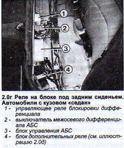
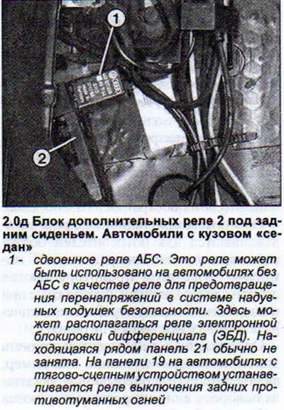
Some relays are mounted on a block located under the rear seat of the car (see illustrations 2.0g and 2.0d).
When the corresponding consumer is switched on, the voltage supplied to terminal 86 closes the electrical circuit via terminal 85 (ground). The magnetic coil inside the relay attracts the contact and thus closes the circuit of the working current. The working current flows to terminal 30, and from there through terminal 87 further to the consumer. Sometimes the relay has terminal 87a, which is rigidly connected to terminal 87.
Switching relays - testing
There should be constant voltage at terminal 30, except in cases where the current consumer depends on another relay, for example, the rear fog light relay is supplied with power only after the lighting is turned on.
To check the power supply, remove the relay from the unit and connect a tester with a control lamp to terminal 30 of the relay base. If the lamp does not light, then there is a break in the line.
1. Connect terminal 86 to the positive (+) battery terminal and terminal 85 to the negative (-). If the relay is working properly, you should be able to clearly hear the coil pulling the relay contact. Otherwise, the relay is faulty. If you don't have a known good relay at hand, you can install a jumper on the relay to continue the trip.
2. Remove the relay from the holder.
3. Install a jumper by connecting terminals 30 and 87. A regular paper clip can be used as a jumper. This technique provides the same thing that a working relay should do. In order to disconnect the consumer, you need to remove the jumper.
Ignition switch X-contact unloading relay
This contact plays an important role. The unloading relay itself is a normal switching relay.
The X-contact of the ignition switch is supplied with power only when the key in the ignition switch is set to the "Drive" position. All significant consumers of the on-board network, such as the windshield wiper, rear window heater or interior blower fans, are connected to the network via this terminal. This ensures that maximum voltage is supplied to the starter when the engine is started.
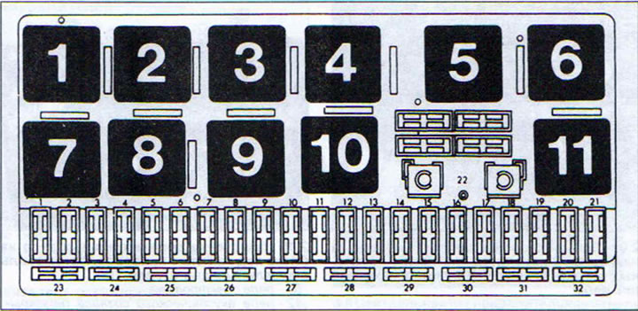
2.0 Central distribution panel. The relays are designated by numbers. The relays have the same designation on the electrical diagrams.
1 - Fog lights and tail lights relay. Cars without fog lights have a jumper in this place.
2 - radiator fan relay (for cars without air conditioning), radiator fan relay for switching on the 2nd stage of rotation
3 - fan relay
4 - headlight washer relay
5 - X-contact of unloading relay
6 - interior blower fan relay (manual air conditioner), air conditioner fan relay for 2nd stage speed (automatic air conditioner)