



Voltage is measured in Volts (V), current in Amps (A), and resistance in Ohms (Ω) (see illustration 1.0).
1.0 The figures in the illustration reflect the order of connecting measuring instruments during measurement
- voltage (left drawing);
- current strength (medium drawing);
- resistance (right picture).
The corresponding measuring device is indicated by a circle with an arrow.
When performing checks and repairs on the on-board electrical system and electronics, various measurements must be taken. In order to perform the required measurement, a suitable measuring instrument is required to ensure the accuracy of the measurements.
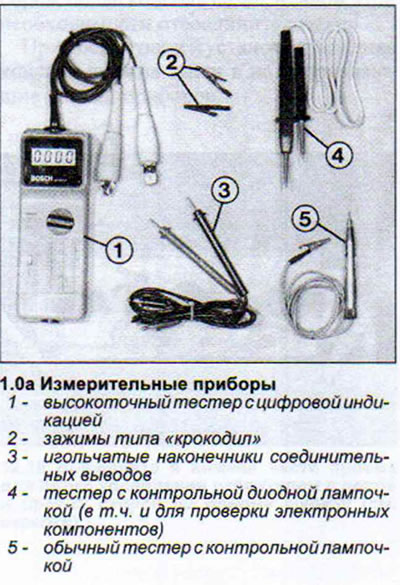
A tester with a regular incandescent bulb is very convenient for performing many types of tests. The tester's connecting terminals have so-called needle tips, which can be used to pierce the insulation of the wire being tested. A tester with a control bulb helps first of all to find out whether there is voltage on the node or component being tested. The degree of glow of the bulb can be used to judge the voltage in the circuit.
As for the electronic unit parts, it is impossible to check for voltage using a tester with a regular incandescent bulb. The part being checked can be damaged. In such cases, a tester with a control diode bulb is used for checking.
More accurate data can be obtained by measuring voltage using a voltmeter with an arrow or digital display. Due to the fact that the voltmeter consumes an insignificant amount of current, it can be used for measurements on electronic components (see illustration 1.0a).
High voltages and high temperatures are dangerous for electronic components. Therefore, when working on the on-board network, certain precautions must be taken.
- a) Turn off the ignition before disconnecting the power plug of the electronic device, or better yet, disconnect the battery.
- b) Disconnect the battery and plugs of the relevant electronic devices when performing welding work on the body.
- c) Do not expose the car to high temperatures for a long time. When placing the car in a drying chamber after painting, its temperature should not exceed 95°C. If the car is to be in the drying chamber for about two hours, the temperature in the chamber should not exceed 85°C.
- d) Start the engine only after the body has (for example, after the drying chamber) cools down to the ambient temperature.
The wiring in a car only appears to be chaotic at first glance. Many connections are standardized, and many digital designations of parts and terminals are generally accepted
Power from the ignition switch is supplied to terminal 15 only when the ignition is on. In this case, in addition to the ignition coil, power is supplied to those consumers of the on-board network that should receive it when the car is moving. The wires on terminal 15 have black insulation and only sometimes with additional colored stripes.
Terminal 30 is constantly supplied with power from the positive terminal of the battery or from the generator when the engine is running. This should be taken into account to avoid short circuits when performing repairs without disconnecting the terminal of the "ground" (-) wire from the battery. This wire usually has red insulation, sometimes with additional coloring.
Terminal 49 is connected to the turn signal and hazard warning flasher.
Terminal 53 supplies power to the windshield wiper motor.
Terminal 56 supplies power to the low beam headlights (the wires have yellow and yellow-black insulation), and high beam. These wires have white or white and black insulation.
Terminal 58 supplies the parking light bulbs, as well as the rear side lights and license plate lights. The main color of the insulation of these wires is gray, sometimes with additional color stripes.
Terminal 31 is the "ground" (-) terminal, through which each consumer of electrical energy is connected to the car body. The corresponding wire has brown insulation.
Individual wires are usually combined into bundles, which in turn are in a black sheath. This makes it difficult to find a specific wire. In this case, it is recommended to navigate using multi-pin connector plugs. Their location and the number of wires connected to them are indicated on the corresponding electrical diagram.
The cross-section of the supply cable depends on the needs of the respective consumer. For a control lamp, a 0.5 mm² wire is sufficient. The starter requires a supply cable with a cross-section of 16 mm². If you install a cable with a smaller diameter than required, such a cable will heat up and the voltage in the circuit will decrease.
The connecting plugs have a mechanical lock that prevents them from being disconnected spontaneously. These locks can be of different types. For example, the plugs of the petrol injection system and the diesel fuel system have wire clamps that need to be pressed to disconnect the plug. Most plugs have locking protrusions on the body that need to be compressed when disconnecting the plugs.
[The original version is on the portal «AUDIMANUAL.ru»]