
Table of contents: Removal ↓ Installation ↓
Attention! Modification of the cylinder head is not permitted.
Attention! When dismantling the vacuum pump, it should be turned in the direction of the arrow, after unscrewing the bolts 1 (see inset in Illustration 4.0).
Removal
1. Disconnect the negative (-) battery terminal from the battery.
2. Drain the coolant.
3. Remove the front bumper (see the relevant chapter).
4. Set the upper front cross member to the service position (see points 3.1-3.6).
5. Remove the timing belt of the gas distribution mechanism drive from the camshaft gears (see the relevant chapter).
6. Remove the gears from the camshafts.
7. Remove the intake manifold (see the relevant chapter).
Right cylinder head
8. Unscrew the mounting bolts (see arrows in the illustration) and remove the right rear part of the timing cover.
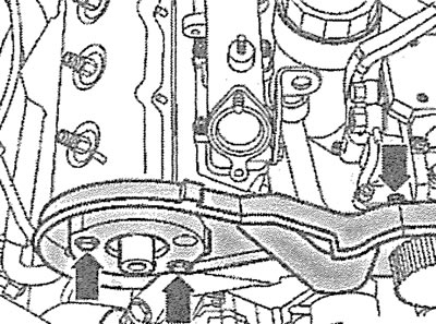
4.8/ Unscrew the mounting bolts (see arrows) and remove the right rear part of the timing cover
9. Unscrew the mounting bolts and disconnect the dipstick guide tube by pushing it upwards.
10. Disconnect the exhaust manifold with the connecting pipe from the cylinder head.
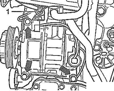
11. Unscrew the mounting bolts (see arrows in the illustration) and remove the turbocharger heat shield.
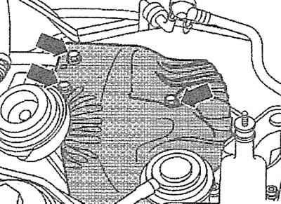
4.11. Unscrew the mounting bolts (see arrows) and remove the turbocharger heat shield
12. Unscrew the union nuts and disconnect the high-pressure fuel lines from the fuel injectors, having first marked the fuel lines.
13. Disconnect the turbocharger and mechanical EGR valve hoses (see arrows in the illustration).
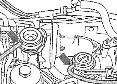
4.13. Disconnect the turbocharger and mechanical EGR valve hoses (see arrows)
14. Remove the mounting clamps (see arrows in the illustration) and disconnect the air duct if the air filter has not been removed before.
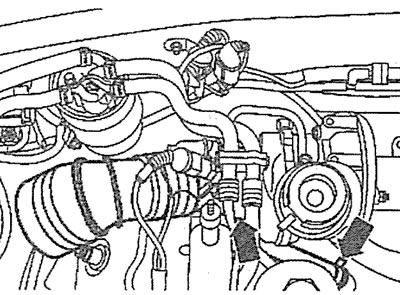
4.14. Remove the mounting clamps (see arrows) and disconnect the air duct
15. Disconnect plugs 1, 2 and 3, as well as plug 4 of the high-pressure fuel pump and plug 5 of the coolant temperature sensor (see illustration).
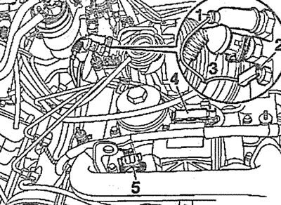
4.15. Disconnect plugs 1, 2 and 3, as well as plug 4 of the high-pressure fuel pump and plug 5 of the coolant temperature sensor
16. Disconnect the glow plug power connectors and move the wiring harness away from the work area.
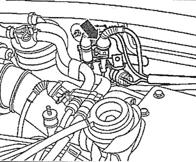
17. Disconnect the plug (see arrow in illustration), located on the right engine mount and move the wiring harness away from the work area.
4.17. Disconnect the plug (see arrow), located on the right engine mount and move the wiring harness away from the work area
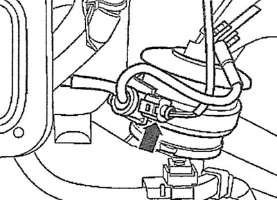
18. Release the plug (see arrow in illustration) the injector needle stroke sensor from the holder and disconnect it.
4.18. Release the plug (see arrow) needle stroke sensor from the holder and disconnect it
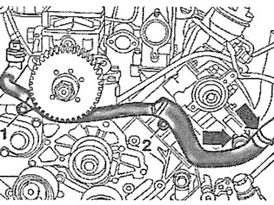
19. Disconnect the oil line from the turbocharger by unscrewing nut 1, and the oil line from the cylinder block by unscrewing nut 2 (see illustration).
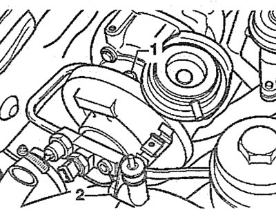
4.19. Disconnect the oil line from the turbocharger by unscrewing nut 1, and the oil line from the cylinder block by unscrewing nut 2
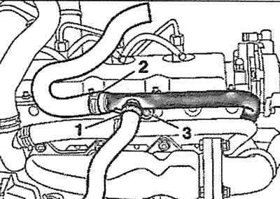
20. Unscrew bolts 2 and 3 and move hose 1 of the cooling system away from the work area (see arrow in illustration).
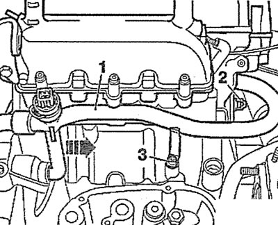
4.20. Unscrew bolts 2 and 3 and move hose 1 of the cooling system away from the work area (see arrow)
21. Disconnect the return fuel line 1 from the fuel injectors and move the common return fuel line away from the work area (see illustration).
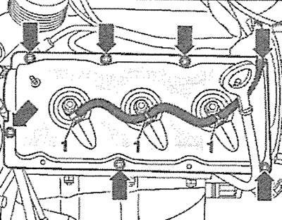
4.21. Disconnect the return fuel line 1 from the fuel injectors and move the common return fuel line away from the work area
22. Unscrew the fastening nuts (see arrows in illustration 4.21) and remove the cylinder head cover.
23. Unscrew the bolts securing the right cylinder head in the sequence shown in the illustration and remove the head. Place the removed cylinder head on a soft pad to avoid damaging the injectors and glow plugs.
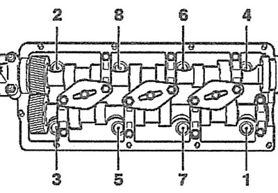
4.23. Unscrew the bolts securing the right cylinder head in the specified sequence
Left cylinder head
24. Unscrew the mounting bolts (see arrows in the illustration) and remove the upper 2, right 1 and left 3 parts of the rear timing cover.
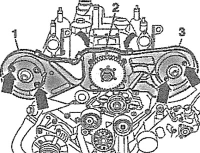
4.24. Unscrew the mounting bolts (see arrows) and remove the upper 2, right 1 and left 3 parts of the rear timing cover
25. Remove the mounting clamps (see arrows in the illustration), unscrew bolts 1 and 2 and remove the cooling system pipe.
4.25. Remove the mounting clamps (see arrows), unscrew bolts 1 and 2 of the fastening and remove the cooling system pipeline
26. Cars with AFB, AKN engines. Disconnect the inlet pipe with the catalytic converter from the exhaust manifold and remove the exhaust manifold together with the connecting pipe.
27. Cars with AFB,AKN engine. Disconnect the air pipe from the turbocharger.
28. Cars with AKE, AYM, BAU, BCZ, BDG, BOH, BFC engines. Remove the pre-catalyst, then disconnect the inlet pipe with the catalytic converter from the exhaust manifold and remove the exhaust manifold together with the connecting pipe.
29. Disconnect plug 1 of the air conditioning compressor regulating valve (see illustration) and move the wiring harness away from the work area.
4.29. Disconnect plug 1 of the air conditioning compressor regulating valve and move the wiring harness away from the work area
30. Disconnect the plug (see arrow in illustration) intake manifold air pressure sensor, release it from the holder and move the wiring harness away from the work area.
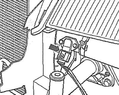
4.30. Disconnect the plug (see arrow) intake manifold air pressure sensor
31. Disconnect the glow plug power connectors, then disconnect the fuel injection pump connector.
32. Cars with ARV, AKE, AKN, AYM, BAU, BCZ, BFC engines. Unscrew the mounting bolts and remove the mechanical valve 1 of the EGR system (see illustration).
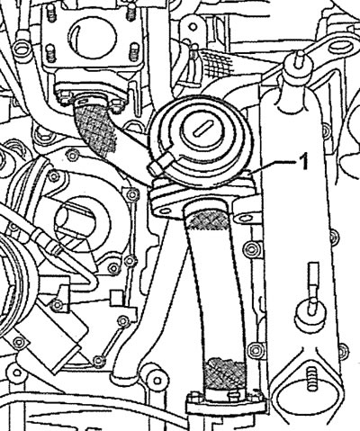
4.32. Unscrew the mounting bolts and remove the mechanical valve 1 of the exhaust gas recirculation system. Cars with AFB, AKE, AKN, AYM, BAU, BCZ, BFC engines
33. Cars with AFB, AKE, AKN, AYM, BAU, BCZ, BFC engines. Remove clamps 1 and 2 and disconnect the cooling system hoses from the pipes by unscrewing bolt 3 (see illustration).
4.33. Remove clamps 1 and 2 and disconnect the cooling system hoses from the pipes by unscrewing bolt 3. Cars with AGV, AKE, AKN, AYM, BAU, BCZ, BFC engines
Caution! Illustration 4.33 shows the cooling system hoses with the engine removed.
34. Unscrew the bolt (see arrow in illustration) and disconnect the cooling system pipe from the cylinder head.
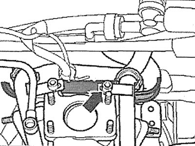
4.34. Unscrew the bolt (see arrow) and disconnect the cooling system hose from the cylinder head
35. Disconnect the return fuel lines 1 from the fuel injectors and move the common fuel line away from the work area (see illustration).
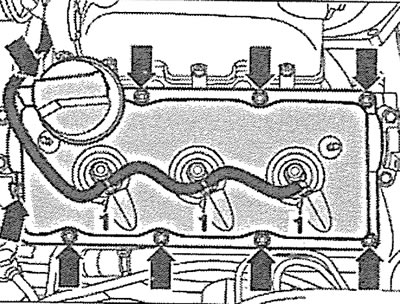
4.35. Disconnect the return fuel lines 1 from the fuel injectors and move the common fuel line away from the work area
36. Unscrew the nuts(see arrows in illustration 4.35) fastenings of the left cylinder head cover and remove the cover.
37. Unscrew the cylinder head mounting bolts in the sequence shown in the illustration and remove the head from the block. Place the removed cylinder head on a soft pad to avoid damaging the glow plugs and fuel injectors.
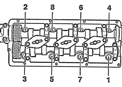
4.37. Unscrew the cylinder head mounting bolts in the specified sequence and remove the head from the block
Installation
The cylinder head is installed in the reverse order of removal.
38. Check the condition of the cylinder head and ensure there are no cracks or dents.
39. Clean the threads of the cylinder head bolt holes. There should be no oil or other contaminants in these holes. If necessary, blow out the holes with compressed air or clean them with a screwdriver wrapped in a rag that absorbs liquid. Oil can be collected from the holes with a grease gun. If this is not done, then when screwing in the bolts, excess pressure will be created in the holes, which can lead to a rupture of the cylinder block or incorrect tightening torque of the bolts.
40. Remove the remains of the old seal from the surface of the cylinder block and head using a plastic scraper. Do not allow dirt and seal remains to get into the cylinder bores. Cover the cylinder bores with a rag.
Attention! Cleaning the sealing surfaces with a metal brush or other metal tool is not permitted.
41. Check the cylinder head for warpage, deformation or distortion using a feeler gauge and a steel ruler (see illustration). The maximum permissible head warpage must not exceed 0.1 mm. Cylinder head modification is not permitted.
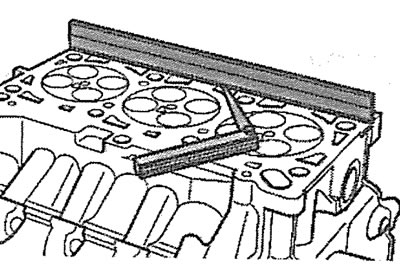
4.41. Check the cylinder head for distortion, deformation or warping using a steel ruler
42. Inspect the removed cylinder head gasket and, if the pistons, connecting rods or crankshaft have not been replaced, install a new gasket of the same thickness as the old one (see illustration). The marking "Oben/Top" on the gasket must face upwards, towards the cylinder head, when it is installed.
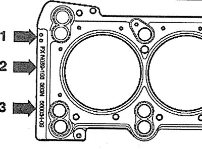
4.42. Cylinder head gasket: 1 - marking holes; 2 - article number according to the spare parts catalogue; 3 - manufacturer's code/marking
43. Cylinder head gasket (see illustration 4.42) may have up to three marking holes depending on the thickness, which in turn depends on the amount of piston protrusion. Measure the piston protrusion from the cylinder block using special devices to select a head gasket of the required thickness (see illustration). To do this, turn the crankshaft and set the pistons to TDC one by one. The piston protrusion is calculated as the average value of the measurement results at two points.
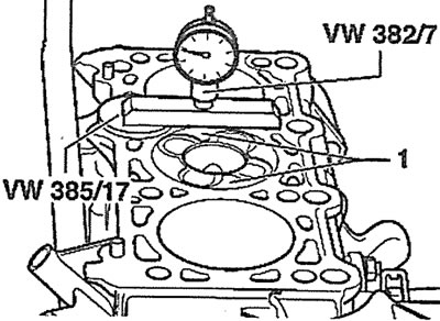
4.43. Measure the piston protrusion from the cylinder block to select the correct cylinder head gasket thickness
| Piston protrusion, mm | Number of marking holes on the gasket |
| 0,39-0,49 | 1 |
| 0,49-0,54 | 2 |
| 0,54-0,65 | 3 |
Attention! The maximum difference in the protrusion of two adjacent pistons should not be more than 0.10 mm.
Caution: The new cylinder head gasket must be removed from the packaging immediately before installation.
44 Tighten the cylinder head bolts in several passes in the sequence shown in the illustration:
- 1st pass - tighten the bolts to 35 Nm;
- 2nd pass - tighten the bolts to 60 Nm;
- 3rd pass - tighten the bolts by 90°;
- 4th pass - tighten the bolts 90° further.
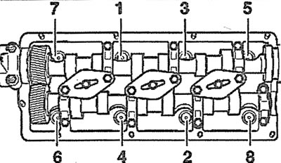
4.44. Tighten the cylinder head bolts in several passes in the sequence shown
This article was copied from the website AudiManual.ru