
Table of contents: Removal ↓ Installation ↓
Removal
1. Cars with parking heater. Unscrew the bolts (see arrows in the illustration) fastening the heater pipe to the soundproofing shield.
5.1. Unscrew the bolts (see arrows)fastening the heater pipe to the soundproofing shield. Cars with a parking heater
2. Unscrew bolts/remove fasteners 1-3 and 5 and remove the front part of the engine splash guard (see illustration).
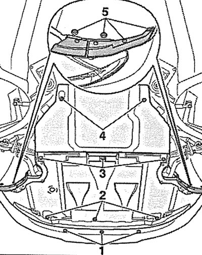
5.2. Unscrew bolts/remove fasteners 1-3 and 5 and remove the front part of the engine mudguard
3. Remove the front bumper (see the relevant chapter).
4. Set the upper crossbar to the service position(see points 3.1-3.6).
5. Remove the timing belt of the gas distribution mechanism drive from the camshaft gears (see the relevant chapter).
6. Remove the right camshaft gear.
7. Remove the cylinder head cover.
8. Unscrew the bolts (see arrows in the illustration) fasteners and remove the upper 2, then the right 1 and left 3 parts of the timing drive protective cover.
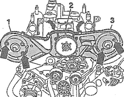
5.8. Unscrew the bolts (see arrows) fasteners and remove the upper 2, then the right 1 and left 3 parts of the timing drive protective cover
9. Unscrew the mounting bolts (see arrows in the illustration), remove the injector holders and then carefully remove the injectors.
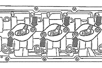
5.9. Unscrew the mounting bolts (see arrows), remove the injector holders and then carefully remove the injectors
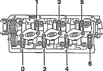
10. Make sure that the camshaft bearing caps have alignment marks. If there are no marks, mark each bearing so that they can be installed in the correct locations during assembly. Number the bearings starting from the flywheel side.
11. Loosen the camshaft bearing cap bolts, then completely unscrew the bolts in a cross pattern and remove the bearing caps.
12. Remove the rocker arm shaft, marking their mounting position.
13. Remove the camshaft from the cylinder head together with the oil seal.
14. Label each tappet and remove the tappets, placing them in a box with numbered compartments, as the tappets must be installed in their original locations during assembly.
Installation
15. Check the condition of the bearing surfaces and camshaft cams for wear and mechanical damage. If any damage is found, replace the camshaft with a new one.
16. Check the working surfaces of the bearings in the camshaft housing in the cylinder block, as well as the bearing caps for scoring or other damage. If any are found, replace the cylinder head with a new one.
17. Inspect the camshaft tappets and if there are any scoring, scratches or other signs of wear, replace the tappets with new ones.
18. Make sure that the crankshaft is secured with locking pin 3242 (see illustration 2.38).
19. Unscrew the pin (see arrow in illustration), located in front of the retaining groove of the exhaust camshaft.
5.19. Unscrew the pin (see arrow), located in front of the retaining groove of the exhaust camshaft
20. Install the thrust half rings of the camshaft axial bearing (see illustrations 5.0 and 5.0a).
21. Install the rocker arm shaft.
22. Position the intake camshaft so that the camshaft locking tool, part number 3458, can be installed without obstruction (see illustration).
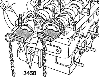
5.22. Install the intake camshaft so that the camshaft locking tool 3458 can be installed without obstruction
23. Install and secure with bolts camshaft bearing caps 1 and 5, observing their markings and preventing the caps from shifting(see illustrations 5.23 and 5.23a).
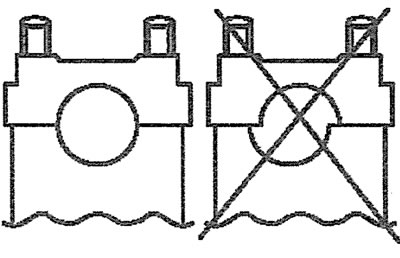
5.23. Install the camshaft bearing caps, making sure not to allow the caps to shift |
5.23a. Install and secure with bolts camshaft bearing caps 1 and 5 |
24. Position the exhaust camshaft so that the camshaft locking tool, part number 3458, can be installed without obstruction (see illustration 5.22).
25. Install and secure with bolts the camshaft bearing caps 0 and 4 (see illustration 5.23a).
26. Again check that the camshafts can be locked with tool 3458 (see illustration 5.22).
Attention! Before installing the front and rear camshaft bearing covers, they must be sealed with sealant, for which follow these steps:
27. Completely remove any remaining sealant from the contact surface of the cylinder head and camshaft bearing caps, then thoroughly clean the contact surfaces; they must be free of oil and grease.
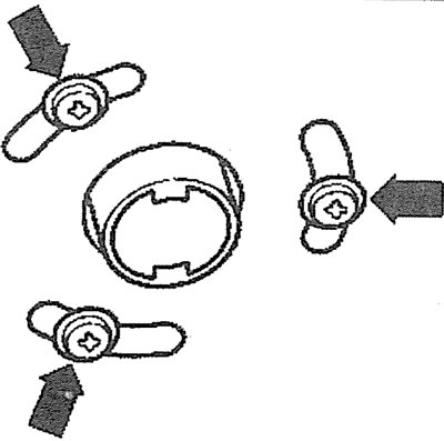
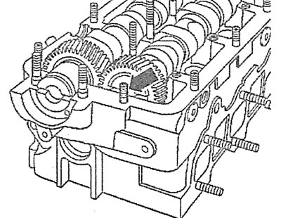
28. Apply a thin layer of sealant to the shaded areas of the front left and rear right outer camshaft bearing caps (see illustration).
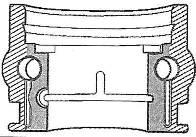
5.28. Apply a thin layer of sealant to the shaded areas of the front left and rear right outer camshaft bearing caps
29. Apply a thin layer of sealant to the shaded areas of the rear left and front right outer camshaft bearing caps (see illustration).
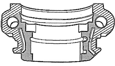
5.29. Apply a thin layer of sealant to the shaded areas of the rear left and front right outer camshaft bearing caps
Caution! Avoid getting sealant on unshaded areas (see illustrations 5.28 and 5.29).
30. Install and bolt the remaining camshaft bearing caps 3, 2 and 6 (see illustration 5.23a).
31. Screw in the stud(see arrow in illustration 5.19), located in front of the retaining groove of the exhaust camshaft.
Next, the installation of the dismantled components is carried out in the reverse order of removal.
(The original article is available on the online resource Audimanual.ru)