
Table of contents: Removal ↓ Installation ↓
Removal
Attention! The engine is removed without the gearbox.
1. Remove the fairing grille.
2. Disconnect the ground (-) wire terminal from the negative battery terminal, after turning off the ignition.
3. Unscrew bolts/remove fasteners 1-5 and remove engine splash guard (see illustration).
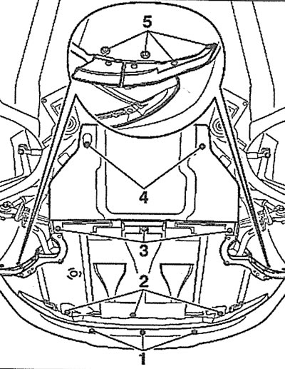
6.3. Unscrew bolts/remove fasteners 1-5 and remove engine splash guard
4. Unscrew the mounting bolts (see arrows in the illustration) and remove the mudguard bracket.
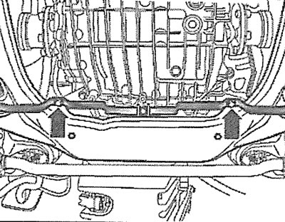
6.4. Unscrew the mounting bolts (see arrows) and remove the mudguard bracket
5. Remove the front bumper (see the relevant chapter).
6. Remove clamp 1 and disconnect the intercooler pipe (see illustration).
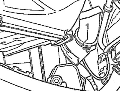
6.6. Remove clamp 1 and disconnect the intercooler pipe
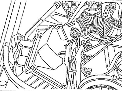
7. Remove the air filter cover 2, and then disconnect the air intake 1 (see illustration).
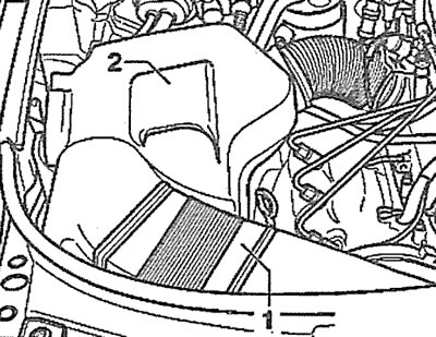
6.7. Remove the air filter cover 2, and then disconnect the air intake 1
8. Remove the engine protective cover by removing the plugs and unscrewing the nuts (see arrows in the illustration).
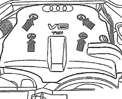
6.8. Remove the engine protective cover by removing the plugs and unscrewing the nuts (see arrows)
9. Unscrew the bolt (see arrow in illustration) and remove the coolant hose holder.
6.9. Unscrew the bolt (see arrow) and remove the coolant hose holder
10. Disconnect the air duct 1 connecting the intercooler and the intake manifold.
6.10. Disconnect the air duct 1 connecting the intercooler and the intake manifold
11. Set the upper front cross member to the service position (see points 3.1-3.6).
12. Unscrew the radiator fan with a viscous coupling, holding its hub from turning with a second key (see illustration).
6.12. Unscrew the radiator fan with a viscous coupling, holding its hub from turning with a second key
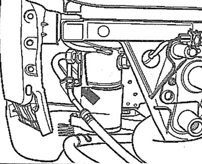
13. Remove the power steering fluid reservoir protective cover (see arrow in illustration).
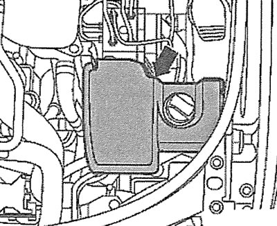
6.13. Remove the protective cover of the power steering reservoir (see arrow)
14. Disconnect the plug (see arrow in illustration) air conditioning compressor electromagnetic valve.
6.14. Disconnect the plug (see arrow) air conditioning compressor solenoid valve
Attention! All work related to the air conditioner should be entrusted to a specialized workshop. Do not open the refrigerant circulation circuit yourself - risk of frostbite!
15. Unscrew the bolts (see arrows in the illustration) and remove the auxiliary drive V-belt protective cover.
6.15. Unscrew the bolts (see arrows) and remove the auxiliary drive V-belt protective cover
16. Unscrew the bolts (see arrows in the illustration) and remove the turbocharger heat shield.
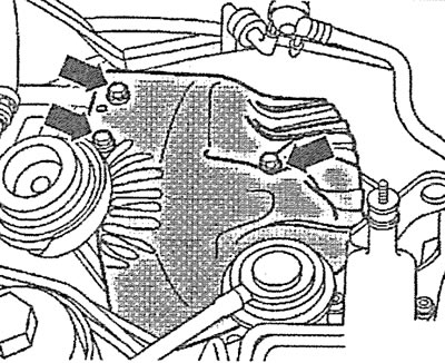
6.16. Unscrew the bolts (see arrows) and remove the turbocharger heat shield
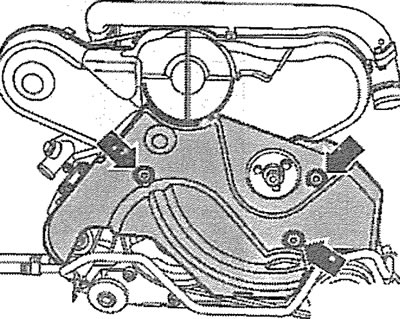
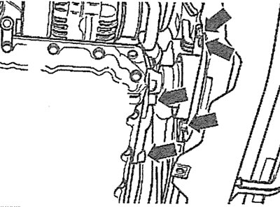
17. Unscrew the mounting bolts (see arrows in the illustration) and disconnect the exhaust pipe.
6.17. Unscrew the mounting bolts (see arrows) intake pipe
18. Unscrew the mounting bolts (see arrows in the illustration) and remove the exhaust pipe together with the catalytic converter.
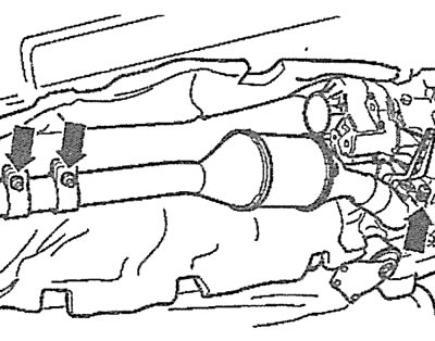
6.18. Unscrew the mounting bolts (see arrows) and remove the inlet pipe together with the catalytic converter
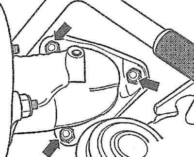
19. Unscrew the bolts (see arrows in the illustration) and remove the engine mount support.
6.19. Unscrew the bolts (see arrows) and remove the engine mount support
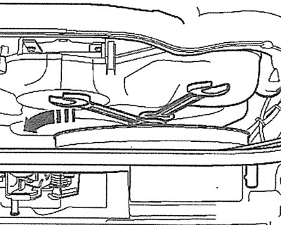
20. Remove the air conditioning compressor drive belt tension roller plug, then loosen the belt tension by loosening bolt A and turning the roller eccentric with torque wrench C, and carefully remove the air conditioning compressor drive belt B (see illustration).
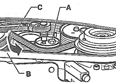
6.20. Loosen bolt A, turn the roller eccentric with torque wrench C and carefully remove the air conditioning compressor drive belt B
Attention! All work related to the air conditioner should be entrusted to a specialized workshop. Do not open the refrigerant circulation circuit yourself - risk of frostbite!
21. Unscrew bolts A and remove the air conditioning compressor without disconnecting the hoses from it (see illustration). Carefully secure the air conditioner compressor to the body with wire, do not allow the air conditioner compressor hoses to bend or twist. When installing, ensure that the centering bushings B are seated correctly.
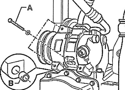
6.21. Unscrew bolts A and remove the air conditioning compressor without disconnecting the hoses from it. When installing, ensure that the centering bushings B are seated correctly
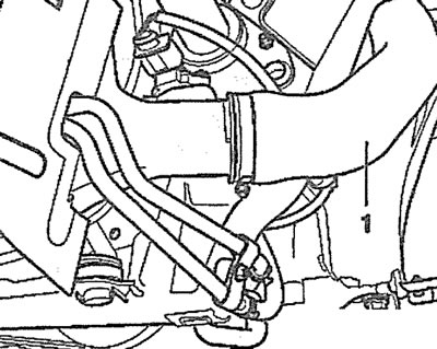
22. Press the plunger of the auxiliary drive V-belt tensioner into the housing using a bent socket wrench, moving it in the direction of the arrow shown in the illustration, and lock the plunger with stop 1.
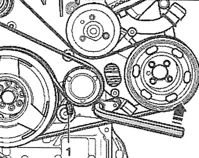
6.22. Press the plunger of the auxiliary drive V-belt tensioner into the housing with a bent socket wrench, moving it in the direction of the arrow, and lock the plunger with stop 1
23. Remove the auxiliary drive V-belt from the power steering pump, generator and radiator fan.
24. Unscrew the mounting bolts (see arrows in the illustration) the V-belt pulley to the crankshaft, holding the pulley from turning with a trunnion key, for example, key 3212.
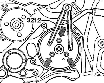
6.24. Unscrew the mounting bolts (see arrows) v-belt pulley to the crankshaft, holding the pulley from turning with a 3212 trunnion key
25. Remove the bracket (see arrow in illustration) power steering pump and move the pump away from the work area without disconnecting the hoses from it.
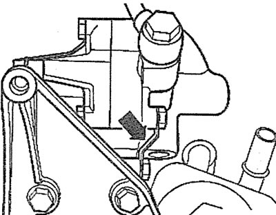
6.25. Remove the bracket (see arrow) power steering pump
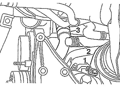
26. Disconnect hose 1 and then plug 2 of the mass air flow sensor and remove the air filter cover together with the supply air duct (see illustration).
6.26. Disconnect hose 1 and then plug 2 of the mass air flow sensor and remove the air filter cover together with the supply air duct
27. Remove the generator (see the relevant chapter).
28. Release the starter wire 1 from the holders by cutting the plastic ties (see arrows in the illustration).
6.28. Release the starter wire 1 from the holders by cutting the plastic ties (see arrows)
29. Disconnect the ground (-) wire 2 from the engine support bracket (see illustration 6.28).
30. Release the plugs 3 from the holders on the right and left engine mounts (see illustration 6.28).
31. Disconnect the wires from the starter and remove the starter.
32. Unscrew the lower gearbox mounting bolts to the engine, marking them and their mounting position.
33. Unscrew the screw plug 2 and drain the coolant (see illustration).
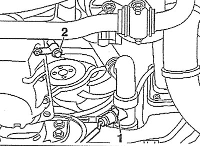
6.33. Unscrew the screw plug 2 and drain the coolant
Attention! The cooling system may have an additional drain hole, closed with a plug, or be without one. In this case, the coolant is drained through the hole for fastening the coolant temperature sensor.
34. Engines with an additional threaded drain plug for coolant. Unscrew the plug from the coolant drain hole on the outlet pipe and drain the liquid.
35. Engines without an additional hole for draining the coolant. Remove the bracket 1 that holds the coolant temperature sensor, remove the sensor and drain the coolant (see illustration 6.33).
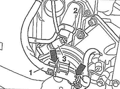
36. Disconnect hose 1 from the oil radiator, then remove clamps 2 and 3 and disconnect the coolant circulation hoses (see illustration).
6.36. Disconnect hose 1 from the oil radiator, then remove clamps 2 and 3 and disconnect the coolant circulation hoses
37. Disconnect the hoses from the coolant reservoir by removing clamps 2, unscrew bolts 1 and remove the coolant reservoir, then disconnect the coolant level sensor plug (see illustration).
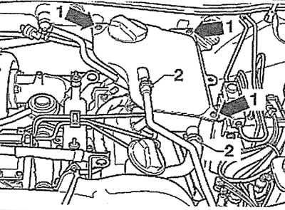
6.37. Disconnect the hoses from the coolant reservoir by removing clamps 2, unscrew bolts 1 and remove the coolant reservoir
38. Disconnect the plug (see arrow in illustration) injector needle stroke sensor and release the sensor wire from the holder.
6.38. Disconnect the plug (see arrow) needle stroke sensor and release the sensor wire from the holder
39. Disconnect the hose with the check valve from the vacuum pump (see arrow in illustration).
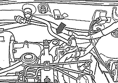
6.39. Disconnect the hose with the check valve from the vacuum pump (see arrow)
40. Disconnect the supply and return fuel lines from the high-pressure fuel pump and move them away from the work area.
41. Disconnect the low pressure hose of the boost pressure regulator and move it away from the work area.
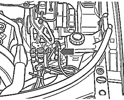
42. Disconnect the supply and return hoses (see arrows in the illustration) from the heater radiator.
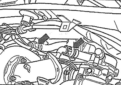
6.42. Disconnect the supply and return hoses (see arrows) from the heater radiator
43. Release the wiring harness from the holders on the gearbox.
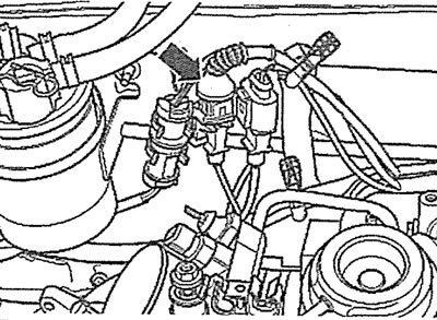
44. Disconnect plugs 1-3, plug 4 of the high-pressure fuel pump, plug 5 of the coolant temperature sensor (see illustration).
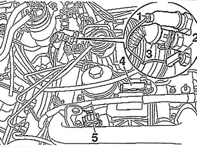
6.44. Disconnect plugs 1-3, plug 4 of the high-pressure fuel pump, plug 5 of the coolant temperature sensor
45. Disconnect the glow plug power connectors and move the glow plug wires away from the work area.
46. Mark the position of the right and left engine mounts and unscrew their lower bolts A (see illustration).
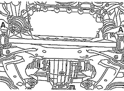
6.46. Mark the position of the right and left engine mounts and unscrew their lower bolts A
47. Remove both gas-filled bonnet struts, secure the bonnet in a vertical position and unscrew the upper gearbox-to-engine mounting bolts.
48. Attach cables or a special crossbar 2024A to the eyes, make sure that all wires and hoses are disconnected from the engine, carefully lift the engine and remove it from the engine compartment (see illustration).
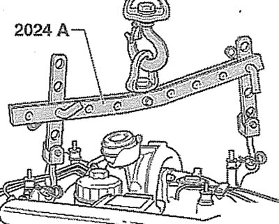
6.48. Attach cables or a special crossbar 2024A to the eyes to lift the engine
Installation
The engine is installed in the reverse order of removal.
49. The tightening torque for the generator mounting bolts to the engine is: M8 bolts - 25 Nm, M10 bolts - 40 Nm.
50. The tightening torque of the air conditioning compressor mounting bolts is 25 Nm.
51. The tightening torque of the bolts of the power steering pump and oil cooler mounting bracket to the engine is 25 Nm.
52. The tightening torque of the front engine mount mounting bolts is 45 Nm.
53. The tightening torque of the bolts securing the exhaust manifold to the cylinder head, as well as the inlet pipe to the turbocharger, is 25 Nm.
54. The tightening torque of the turbocharger heat shield mounting bolts is 10 Nm.
(The original version of the article is posted on the website: «audimanual.ru»)