
Table of contents: Removal ↓ Installation ↓
Removal
1. Remove the upper engine cover by removing the plugs and unscrewing the nuts (see arrows in the illustration).
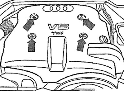
9.1 Remove the upper engine protective cover by removing the plugs and unscrewing the nuts (see arrows)
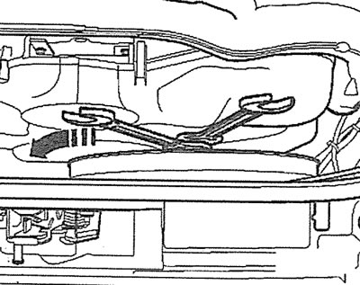
2. Cars with a parking heater. Unscrew the bolts securing the heater pipe to the soundproofing shield (see arrows in the illustration).
9.2. Unscrew the bolts securing the parking heater pipe to the soundproofing shield (see arrows). Cars with parking heater
3. Unscrew bolts/remove fasteners 1-3 and 5 and remove the front part of the engine splash guard (see illustration).
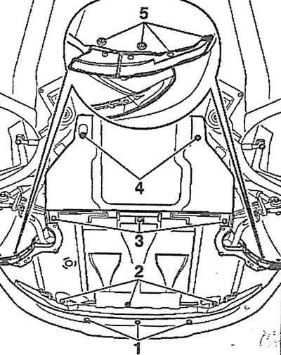
9.3. Unscrew bolts/remove fasteners 1-3 and 5 and remove the front part of the engine mudguard
4. Unscrew the radiator fan with a viscous coupling, holding its hub from turning with a second key (see illustration).
9.4. Unscrew the radiator fan with a viscous coupling, holding its hub from turning with a second key
5. Remove the mounting clamps (see arrows in the illustration) and remove the left and right parts of the timing gear protective cover.
9.5. Remove the mounting clamps (see arrows) and remove the left and right parts of the timing gear protective cover
6. Unscrew the mounting bolts (see arrows in the illustration) and remove the auxiliary drive V-belt protective cover.
9.6. Unscrew the mounting bolts (see arrows) and remove the auxiliary drive V-belt protective cover
7. Remove the oil pan (see the relevant chapter).
8. Remove the cap from the low-fill neck.
9. Set the piston of cylinder No.1 to TDC by turning the crankshaft in the direction of engine rotation by the central bolt of the drive gear until the inscription "OT" appears in the hole of the oil filler neck (top dead center) on the camshaft (see illustration).
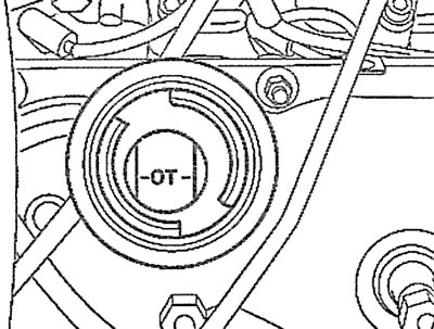
9.9. Turn the crankshaft in the direction of engine rotation by the central bolt of the drive gear until the inscription "OT" appears in the hole of the oil filler neck (top dead center) on the camshaft
10. Unscrew the plug on the cylinder block and screw in a locking pin of a suitable diameter instead, for example, locking pin 3242, thereby locking the crankshaft (see illustration).
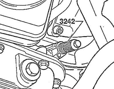
9.10. Unscrew the plug on the cylinder block and screw in the locking pin 3242 instead, thereby locking the crankshaft
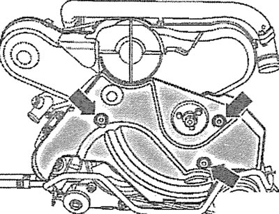
11. Unscrew bolts 1 and remove the oil pump shield, then unscrew bolt 2 from the balance shaft housing (see illustration).
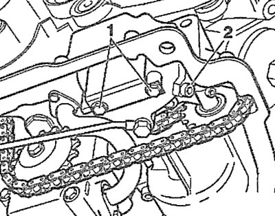
9.11. Unscrew bolts 1 and remove the oil pump shield, then unscrew bolt 2 from the balance shaft housing
12. Lock the balance shaft with a suitable stop, for example stop 3204, by inserting it into the hole for bolt 2 (see illustration).
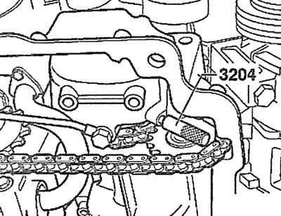
9.12. Lock the balance shaft with stop 3204 by inserting it into the hole for bolt 2
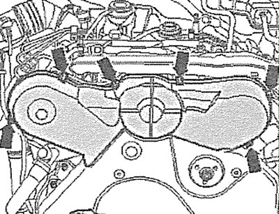
13. Loosen bolt 1 securing the sprocket to the oil pump shaft, unscrew bolt 3 of the balance shaft sprocket and bolts 4 securing the oil line (see illustration).
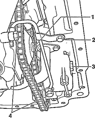
9.13. Loosen bolt 1 securing the sprocket to the oil pump shaft, unscrew bolt 3 of the balance shaft sprocket and bolts 4 securing the oil line
14. Unscrew bolt 2 of the oil line holder and remove the oil line (see illustration 9.13).
15. Unscrew the bolts (see arrows in the illustration) fasteners and remove the pressure oil line.
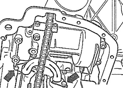
9.15. Unscrew the bolts (see arrows) fasteners and remove the pressure oil line
16. Press the oil pump drive chain with a screwdriver (see illustration).
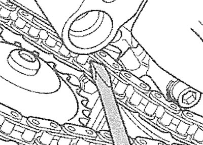
9.16. Press the oil pump drive chain with a screwdriver
17. Unscrew the bolts (see arrows in the illustration) guide sprocket mounts and remove it and the oil pump sprocket.
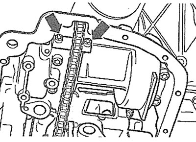
9.17. Unscrew the bolts (see arrows) guide sprocket mounts and remove it and the oil pump sprocket
18. Unscrew the bolts (see arrows in the illustration) oil pump mounts and remove the pump.
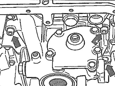
9.18. Unscrew the bolts (see arrows) oil pump mounts and remove the pump
Installation
The oil pump is installed in the reverse order of removal.