
Withdrawal
Lower part of the oil pan
1. Remove the cap from the coolant expansion tank.
Attention!, When the engine is hot, before removing the filler cap of the expansion tank, wrap it with a rag to prevent burns from hot coolant or steam.
2. Vehicles with parking heater. Unscrew the bolts securing the heater pipe to the soundproof shield (see arrows in illustration).
11.2. Unscrew the bolts securing the parking heater pipe to the soundproof shield (see arrows). Vehicles with parking heater
3. Unscrew the bolts/remove the clips 1-3 and 5 and remove the front part of the engine mudguard (see illustration).
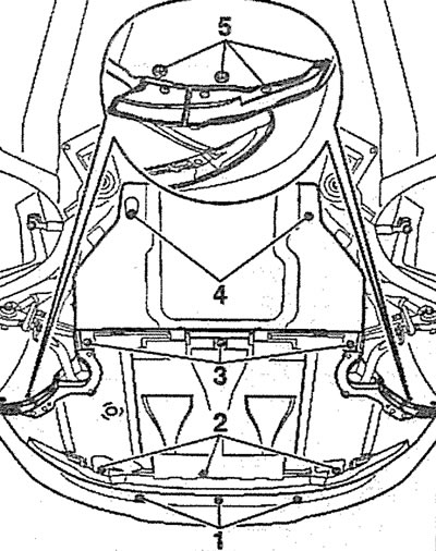
11.3. Unscrew the bolts/remove the clips 1-3 and 5 and remove the front part of the engine mudguard
4. Unscrew bolt 2, disconnect hose 1 from the oil cooler and drain the coolant into a suitable container (see illustration).
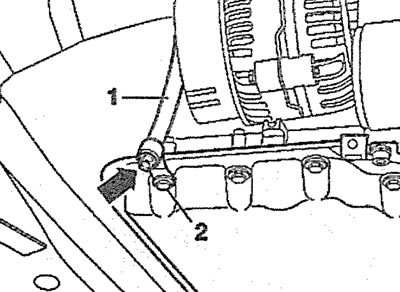
11.4. Unscrew bolt 2, disconnect hose 1 from the oil cooler and drain the coolant into a suitable container
5. Unscrew the bolt (see arrow in illustration) transmission oil circulation pipe holder.
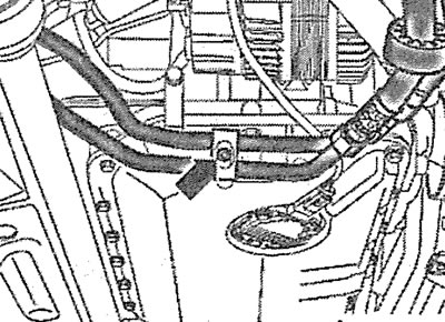
11.5. unscrew the bolt (see arrow) holder for transmission oil lines
6. Disconnect the plug (see arrow in the illustration) engine oil level and temperature sensor.
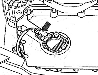
11.6. Disconnect the plug (see arrow) engine oil level and temperature sensor
7. Unscrew the bolts 1 and 2 of the fastening brackets of the anti-roll bar to the subframe (see illustration). Lower the stabilizer bar slightly and tie it with wire.
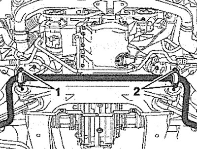
11.7. Unscrew the bolts 1 and 2 of the brackets for attaching the stabilizer bar to the subframe
8. Take the engine oil with a siphon through the dipstick guide tube or drain the oil by unscrewing the drain plug.
9. Unscrew the mounting bolts and remove the lower part 1 of the oil pan (see illustration).
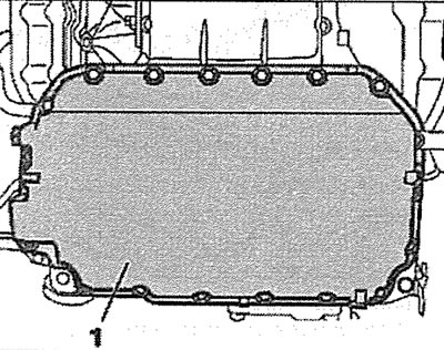
11.9. Unscrew the mounting bolts and remove the lower part 1 of the oil pan
Upper part of the oil pan
10. Disconnect the wire terminal «masses» (-) from the negative pole of the battery.
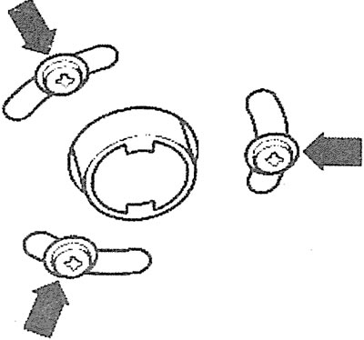
11. Remove the top protective cover of the engine by removing the plugs and unscrewing the nuts (see arrows in illustration).
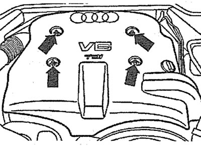
11.11. Remove the top protective cover of the engine by removing the plugs and unscrewing the nuts (see arrows)
12. Drain the coolant.
13. Remove the front bumper (see relevant chapter).
14. Set the upper cross member of the front end to the service position (see paragraphs 3.1-3.6).
Attention! Since the engine mounts must be removed to remove the top of the oil pan, the engine must be lifted with a hoist or other means to relieve the mounts. In specialized workshops, for this, they use a transverse beam installed above the engine compartment (see illustration 11.0a).
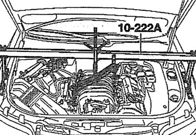
11.0a. In specialized workshops, a cross beam mounted above the engine compartment is used to lift the engine
15. Remove the oil dipstick and disconnect its guide tube from the cylinder block.
16. Remove the ribbed accessory drive belt (see relevant chapter).
17. Disconnect the plug 1 of the pressure reducing valve of the air conditioning compressor, unscrew the bolts securing the compressor to the bracket (see arrows in illustration).
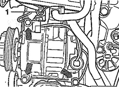
11.17. Disconnect the plug 1 of the pressure reducing valve of the air conditioning compressor, unscrew the bolts securing the compressor to the bracket (see arrows)
18. Tie up the air conditioning compressor, without disconnecting the pipelines from it, with a wire to the subframe (see arrow in illustration).
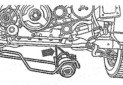
11.18. Tie up the air conditioning compressor, without disconnecting the pipelines from it, with a wire to the subframe (see arrow)
19. Remove the bolts (see arrows in illustration) and remove the A/C compressor bracket.
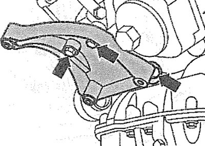
11.19. Unscrew the bolts (see arrows) and remove the A/C compressor bracket
20. Remove the bolts (see arrows in illustration) fasteners, remove the generator and disconnect the plug from it.
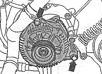
11.20. Unscrew the bolts (see arrows) fasteners, remove the generator and disconnect the plug from it
21. Disconnect its wires 2 and 3 from the starter, unscrew the bolts of its fastening (see arrows in illustration) and remove the starter.
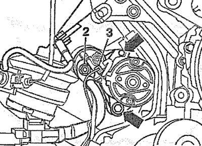
11.21. Disconnect its wires 2 and 3 from the starter, unscrew the bolts of its fastening (see arrows) and remove the starter
22. Unscrew the bolts 1 and 2 of the fastening brackets of the anti-roll bar to the subframe (see illustration 11.7).
23. Release the starter wire from the holder and move it to the side (see arrows in illustration).
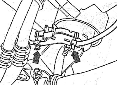
11.23. Release the starter wire from the holder and move it to the side (see arrows)
24. Install a support under the subframe, for example, support 1202A (see illustration).
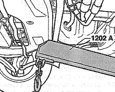
11.24. Install support 1202A under subframe
25. Mark the mounting position of the lower nut 3 on the left and right engine mounts and unscrew the lower nuts on both supports, and also unscrew the bolts 4 and 5 of the support brackets (see illustration).
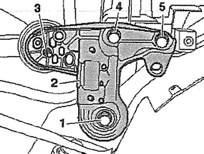
11.25. Mark the mounting position of the lower nut 3 on the left and right engine mounts and unscrew the lower nuts on both mounts, and also unscrew the bolts 4 and 5 of the mount brackets
26. Unscrew the front bolts 1 fastening the left and right sides of the subframe and remove the bracket 2 (see illustration 11.25).
Attention! In order not to subsequently adjust the camber and convergence of the front wheels, it is recommended to unscrew only the front bolts of the subframe and lower only its front part.
27. Loosen the bolt 2 of the gearbox suspension support, unscrew the bolt 1 (see illustration).
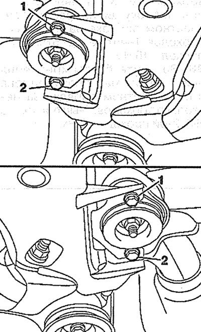
11.27. Loosen the bolt 2 of the gearbox suspension support, unscrew the bolt 1
28. Slowly lower the subframe.
29. Remove the lower part of the oil pan (see points 11.1-11.9).
30. Remove the oil pump (see relevant chapter).
31. Unscrew bolts of fastening of the engine to a transmission near the top part of the oil pallet.
32. Remove the dipstick guide tube from the top of the oil pan.
33. Unscrew the bolts 1 and 2 securing the upper part of the oil pan, move the pan to the left and remove it (see illustration).
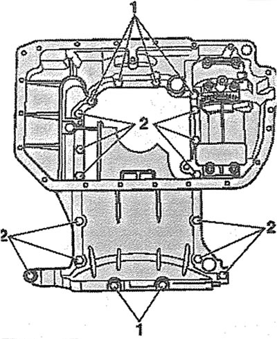
11.33. Unscrew bolts 1 and 2 securing the upper part of the oil pan, move the pan to the left and remove it
34. Remove the bolts (see arrows in illustration) and remove the balance shaft housing from the oil pan.
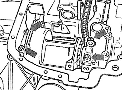
11.34. Unscrew the bolts (see arrows) and remove the balance shaft housing from the oil pan
Installation
The oil pan is installed in the reverse order of removal.
35. Clean the surfaces to be sealed and remove the remnants of the old sealant from them with nozzles using a drill (see illustrations 11.35 and 11.35a).
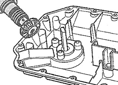
11.35. Clean the sealing surfaces and remove the remnants of the old sealant from them with nozzles using a drill (bottom of oil pan) | 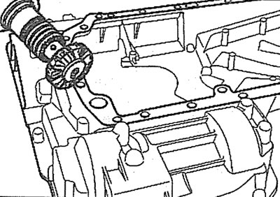
11.35 a.m. Clean the sealing surfaces and remove the remnants of the old sealant from them with nozzles using a drill (top of oil pan) |
36. Apply before installing the oil pan on its mating surface (see arrows in illustrations 11.36 and 11.36a) a layer of sealant about 2-3 mm thick. If more sealant is applied, the excess will enter the engine oil and clog the oil intake strainer.
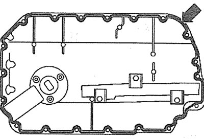
11.36. Apply before installing the oil pan on its mating surface (see arrow) a layer of sealant about 2-3 mm thick (bottom of oil pan) | 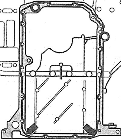
11.36a. Apply before installing the oil pan on its mating surface (see arrows) a layer of sealant about 2-3 mm thick (top of oil pan) |
Attention! After applying the sealant, the pallet should be installed in place no later than 5 minutes later.
Attention! If the oil pan is not sealed with sealant, replace the pan gasket with a new one.
37. Tighten the bolts securing the upper part of the oil pan to the cylinder block in a crosswise manner in several passes: 1st pass - 5 Nm; 2nd pass - 16 Nm.
38. Tighten the bolts of the lower part of the oil pan in a crosswise manner in several passes: 1st pass - 5 Nm; 2nd pass - 10 Nm.
Visitor comments