
Table of contents: Removal ↓ Installation ↓
Depending on the vehicle's configuration, the V-belt can drive various auxiliary units, such as the generator, power steering pump, radiator fan and, if available, the air conditioner.
Removal
Caution! When removing the auxiliary drive V-belt, you will need to set the upper front crossmember to the service position, for which follow these steps:.
1. Unscrew bolts 1-5 and remove the engine splash guard (see illustration).
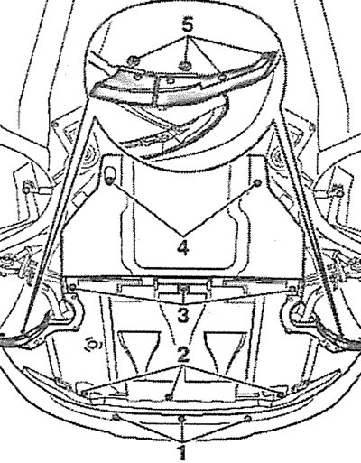
3.1. Unscrew bolts 1-5 and remove the engine splash guard
2. Remove the front bumper (see the relevant chapter).
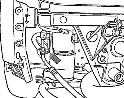
3.3. Unscrew the refrigerant circulation hose holder mounting bolt (see arrow)
3. Unscrew the refrigerant circulation hose holder mounting bolt (see arrow in illustration).
4. Unscrew bolts 3 on the right and left sides of the front panel and replace both bolts with the special device 3369 (see illustration 3.0b) or its replacement.
Attention! If the specified special device is not available, then you can use two M8x90 bolts, on which spacer washers with an outer diameter of 24 mm and a thickness of about 2 mm are installed. In addition, you will need two bushings 80 mm long and 17 mm in diameter.
5. Unscrew bolts 2 from the right and left sides of the upper cross member (see illustration 3.0b).
6. Move the crossbar forward until the bolt hole on the crossbar aligns with the front hole on the wing and in this position secure the crossbar with bolts on the right and left sides.
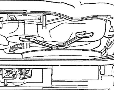
7. Remove the engine protective cover by unscrewing the nuts that secure it (see arrows in the illustration).
3.7. Remove the engine protective cover by unscrewing the nuts that secure it (see arrows)
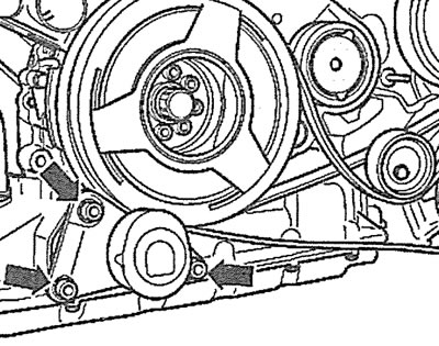
8. Unscrew the radiator fan with a viscous coupling, holding its hub from turning with a second wrench (see illustration).
3.8. Unscrew the radiator fan with a viscous coupling, holding its hub from turning with a second wrench
9. Remove both upper parts of the timing cover.
10. Unscrew the bolts securing the protective cover of the auxiliary drive V-belt (see arrows in the illustration) and remove the lid.
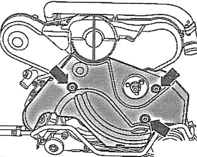
3.10. Unscrew the bolts securing the protective cover of the auxiliary drive V-belt (see arrows) and remove the lid
11. Unscrew the bolts (see arrows in the illustration) and remove the air conditioning compressor support bracket.
3.11. Unscrew the bolts (see arrows) and remove the air conditioning compressor support bracket
Attention! The air conditioning compressor is driven by a separate V-belt (see illustration 3.0a), which must be removed to gain access to the accessory drive belt.
12. Remove the plug that covers the bolt securing the air conditioning compressor drive belt tension roller, loosen the bolt (see arrow in illustration) and remove the belt, having first marked the direction of its movement if the belt is to be reinstalled.
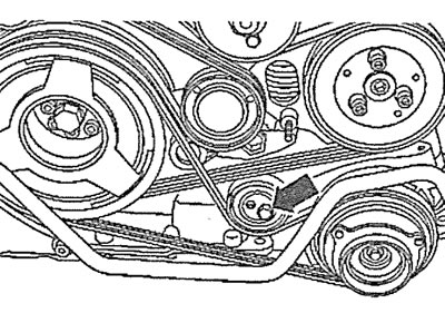
3.12. Loosen the bolt (see arrow) air conditioning compressor drive belt tension roller
13. Loosen the tension of the V-belt of the auxiliary drive. To do this, turn the belt tensioner with a hexagonal socket wrench in the direction of the arrow in the illustration and lock the tensioner in this position by inserting a 4 mm diameter stop into the hole, for example, a special stop, catalog number T10060 (see illustration).
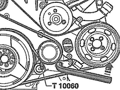
3.13. Turn the accessory drive belt tensioner with a hexagonal socket wrench in the direction of the arrow and lock the tensioner in this position by inserting the T10060 stop into the hole
14. Remove the accessory drive V-belt, having first marked its direction of travel in case the belt is to be reinstalled.
Installation
15. Carefully lay the V-belt of the auxiliary drive, working counterclockwise. First, lay the belt on the belt pulley 1 on the crankshaft, on the guide rollers 4 and 6, and lastly on the tension roller 7 (see illustration).
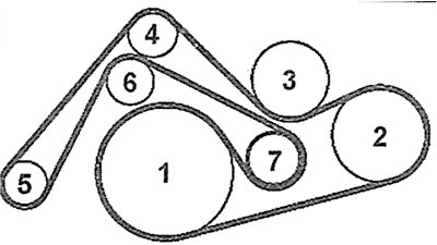
3.15. Sequence of laying the V-belt of the auxiliary drive: 1 - pulley on the crankshaft; 2 - Power steering pump pulley; 3 - radiator fan pulley; 4 - guide roller 1; 5 - generator; 6 - guide roller 2; 7 - tension roller
16. Turn the V-belt tension roller slightly to the left, counterclockwise, with the overhead wrench and remove the stop that held the tensioner in place (see illustration 3.13). After this, slowly release the key along with the tensioner, which will automatically tighten the belt.
17. Place the V-belt B of the air conditioning compressor drive and using a torque wrench C with an 8 mm hexagonal insert, turn the tension roller eccentric to the left with a force of 7 Nm (see arrow in illustration).
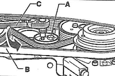
3.17. Place the V-belt B of the air conditioning compressor drive and using a torque wrench C with an 8 mm hexagonal insert, turn the tension roller eccentric to the left with a force of 7 Nm (see arrow)
18. Tighten bolt A of the air conditioning compressor drive belt tension roller with a torque of 22 Nm (see illustration 3.17).
Next, the installation of the dismantled components is carried out in the reverse order of removal.