
Table of contents: Removal ↓ Installation and adjustment ↓
Removal
1. Remove the accessory drive V-belt (see the relevant chapter).
2. Remove the cap from the oil filler neck.
3. Turn the crankshaft in the direction of engine rotation by the central bolt securing the drive gear until the inscription "OT" appears in the hole of the oil filler neck (top dead center) on the camshaft (see illustration).
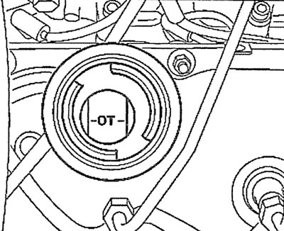
2.3. Turn the crankshaft in the direction of engine rotation by the central bolt of the drive gear until the inscription "OT" appears in the hole of the oil filler neck (top dead center) on the camshaft
4. Unscrew the threaded plug on the cylinder block at approximately the level of the middle cylinder.
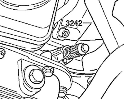
5. Screw in the locking pin, catalog number 3242, instead of the plug (see illustration). Make sure that the pin enters the hole in the crankshaft cheek and locks the shaft.
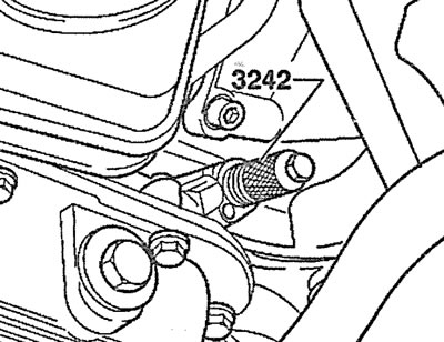
2.5. Screw in the locking pin instead of the plug, catalog number 3242
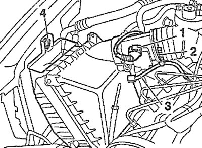
6. Unscrew the coolant expansion tank mounting bolts (see arrows 1 in the illustration).
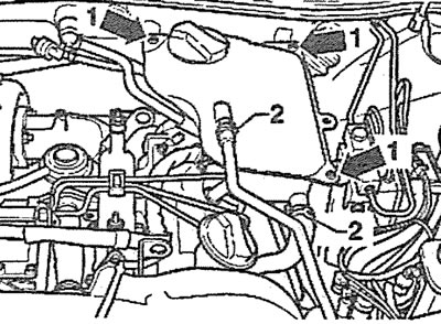
2.6. Unscrew the coolant expansion tank mounting bolts (see arrows 1)
7. Disconnect the coolant level sensor plug at the bottom of the expansion tank and move the tank away from the work area without disconnecting the hoses 2 from it (see illustration 2.6).
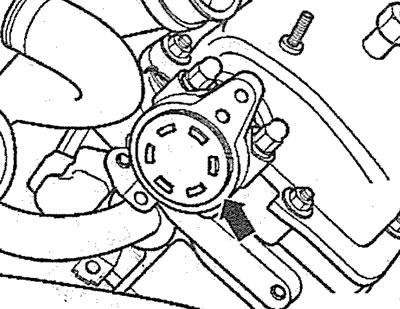
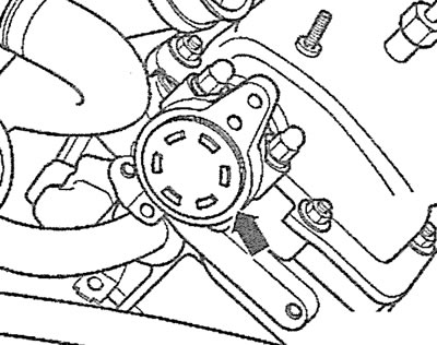
8. Unscrew the bolts 1 securing the vacuum pump and turn the pump on the end face of the left cylinder head to the left (see arrow in illustration).
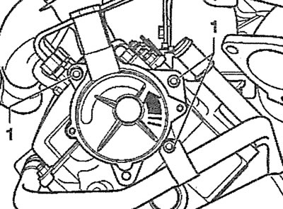
2.8. Unscrew the bolts 1 securing the vacuum pump and turn the pump on the end face of the left cylinder head to the left (see arrow)
9. Remove the vacuum pump by pushing it backwards without disconnecting the low pressure hoses from it.
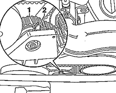
10. Disconnect plug 1 of the mass air flow sensor, then loosen clamp 2 securing the supply air duct to the air filter housing (see illustration).
2.10. Disconnect plug 1 of the mass air flow sensor, then loosen clamp 2 securing the supply air duct to the air filter housing
11. Disconnect hose 3, unscrew bolt 4 and remove the air filter (see illustration 2.10).
12. Unscrew the fastening nut, remove the fuel filter from the bracket and move it away from the work area without disconnecting the fuel lines from it.
13. Unscrew the mounting bolts (see arrows in the illustration) and remove the air duct connecting the turbocharger and intercooler on the right cylinder head.
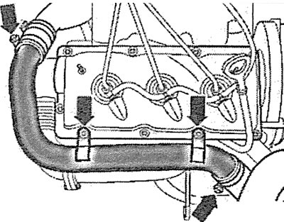
2.13. Unscrew the mounting bolts (see arrows) and remove the air duct connecting the turbocharger and intercooler on the right cylinder head
14. Remove the covers that cover the ends of the camshafts by prying the covers with a screwdriver (see arrow in illustration).
2.14. Remove the covers that cover the ends of the camshafts by prying the covers off with a screwdriver (see arrow)
Attention! The covers are damaged when removed, so they must be replaced after each dismantling. Proceed carefully so as not to damage the seating surface of the cover on the cylinder head.
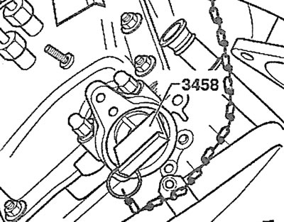
15. Insert the locking plates, catalog number 3458, into the grooves on the ends of the camshafts of both cylinder heads and attach chains to them to prevent the plates from falling out (see illustration). If there are no such stoppers, then use suitable rulers 40 mm wide and 5 mm thick or make the plates yourself.
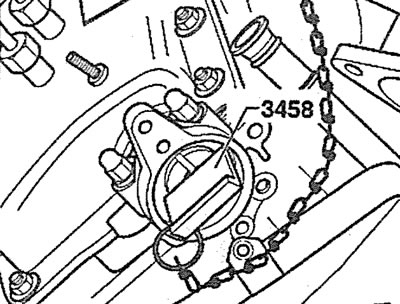
2.15. Insert locking plates, catalog number 3458, into the grooves on the ends of the camshafts of both cylinder heads and attach chains to them to prevent the plates from falling out
Caution! The said locking plates must not be used as a stop to prevent the shafts from turning when unscrewing the camshaft gear mounting bolts.
16. Unscrew bolts 1 and remove the vibration damper from the fuel injection pump gear (see illustrations 2.16 and 2.16a).
2.16. Unscrew bolts 1 and remove the vibration damper from the fuel injection pump gear
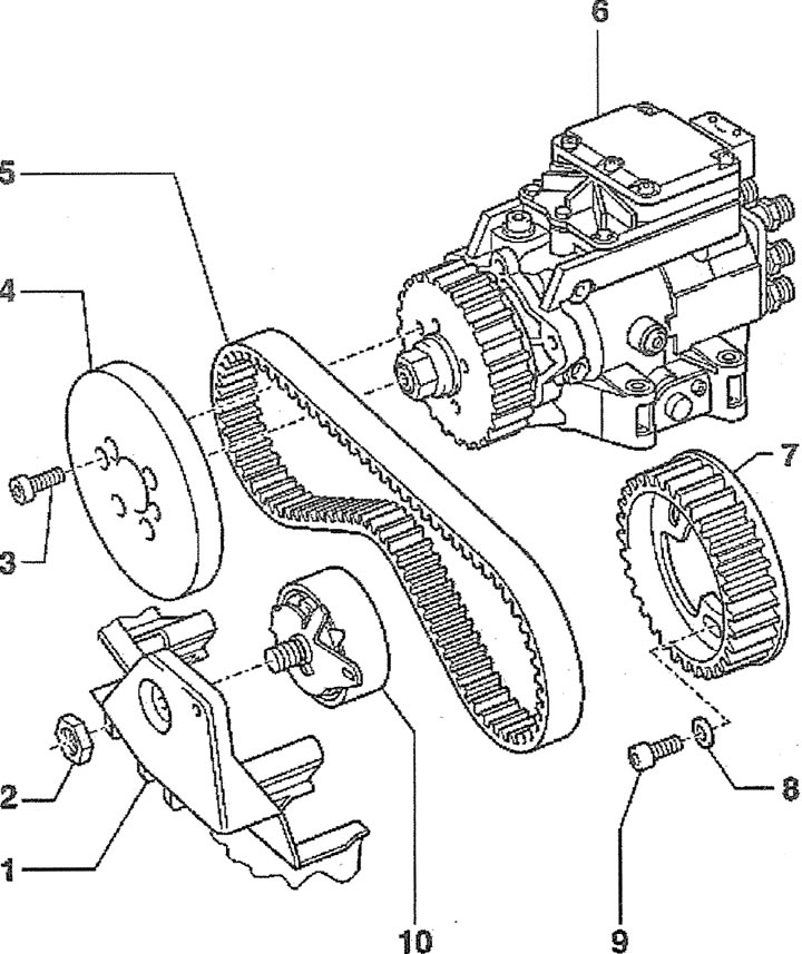
2.16a. High-pressure fuel pump (HPFP) drive:
1 - radiator fan bracket with viscous coupling
2 - nut for fastening the tension roller of the fuel injection pump drive toothed belt. Tightening torque - 36 Nm
3 - bolt for fastening the vibration damper of the fuel injection pump gear. Tightening torque - 22 Nm
4 - vibration damper
5 - fuel injection pump drive toothed belt
6 - high pressure fuel pump (HPFP)
7 - fuel injection pump gear
8 - spacer washer
9 - fuel injection pump gear mounting bolt. Tightening torque - 22 Nm
10 - tension roller of the toothed belt of the fuel injection pump drive
Caution! Do not unscrew nut 2 (see illustration 2.16), as this may lead to a violation of the basic adjustment of the fuel injection pump. Subsequent adjustment of the fuel injection pump is impossible even in a workshop.
17. Mark the direction of the fuel injection pump drive toothed belt with chalk, marker or paint if it is to be reinstalled. Failure to maintain the previous direction of the toothed belt during its further use will result in its damage or breakage.
18. Loosen the tension of the fuel injection pump drive toothed belt by turning the roller with a socket wrench and remove the fuel injection pump drive toothed belt from the camshaft gear (see illustration).
2.18. Loosen the tension of the fuel injection pump drive toothed belt by turning the roller with a socket wrench and remove the fuel injection pump drive toothed belt from the camshaft gear
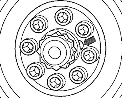
19. Unscrew the eight bolts 1 and remove the accessory drive belt pulley from the crankshaft. The central bolt 2 secures the timing gear to the crankshaft, so there is no need to unscrew the central bolt when removing the belt pulley (see illustration).
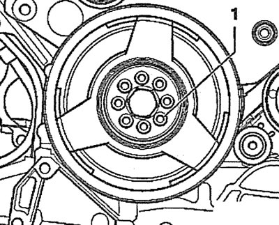
2.19. Unscrew the eight bolts 1 and remove the accessory drive belt pulley from the crankshaft. There is no need to unscrew the central bolt 2
20. Remove the lower part 4 of the timing gear protective cover (see illustration).
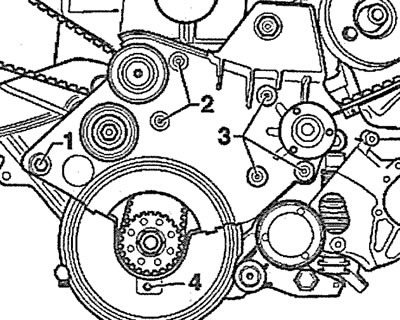
2.20. Remove the lower part 4 of the timing gear protective cover
21. Unscrew bolts 1, 2 and 3 and remove the viscous coupling fan mounting bracket (see illustration 2.20). The guide rollers are also located on this bracket.
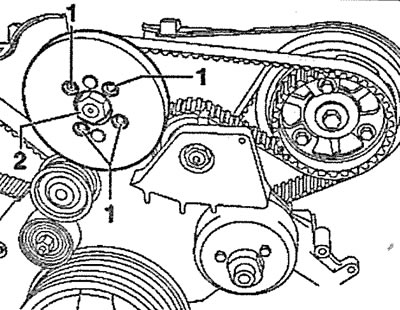
22. Unscrew the three bolts (see arrows in the illustration) and remove gear 1, from which the high-pressure fuel pump is driven by a toothed belt.
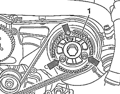
2.22. Unscrew the three bolts (see arrows) and remove gear 1 of the fuel injection pump drive
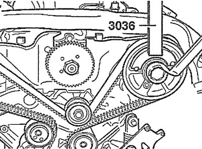
23. Loosen the bolts securing the camshaft gears to their hubs, holding the gears from turning with a special tool, catalog number 3036 (see illustration).
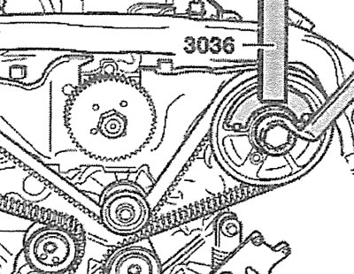
2.23. Loosen the camshaft gear mounting bolts, holding them from turning with a special tool, catalog number 3036
Attention! It is not necessary to completely unscrew the camshaft gear mounting bolts.
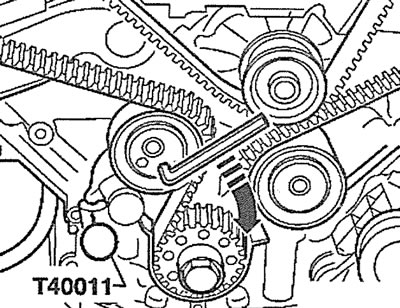
24. Slowly turn the timing belt tension roller with an 8 mm socket wrench to the right (see arrow in illustration) so that the tensioner plunger enters the housing and the holes in the housing and plunger are aligned. Insert a suitable pin, for example, a pin with catalog number T40011, into the aligned holes, thereby fixing the plunger in the tensioner housing.
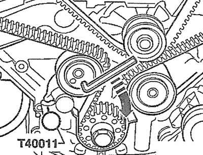
2.24. Slowly turn the timing belt tension roller to the right with an 8 mm socket wrench (see arrow) so that the tensioner plunger enters the housing and the holes on the housing and plunger are aligned. Insert the T40011 pin into the aligned holes
Caution! The timing belt tensioner has an oil-filled plunger and therefore the plunger should be pressed into the tensioner housing slowly with a uniform force. Excessive force may damage the tension roller.
25. Remove the gear together with the toothed belt from the hub of the left cylinder head camshaft using a suitable two-jaw puller, for example, the T40001 puller, resting its bolt against the central bolt of the hub fastening (see illustration).
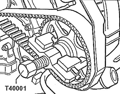
2.25. Remove the gear together with the toothed belt from the hub of the camshaft of the left cylinder head using the two-jaw puller T40001, resting its bolt against the central bolt of the hub fastening
26. Remove the timing belt from the gears and guide rollers.
Installation and adjustment
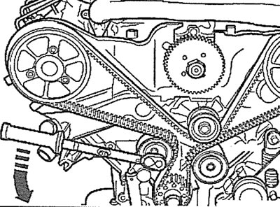
27. Place the toothed belt on the crankshaft gear, then on the camshaft gear of the right cylinder head, the tension and guide rollers and the water pump.
28. Place the toothed belt on the removed camshaft gear of the left cylinder head, then put the gear together with the belt on the shaft hub and screw in the gear mounting bolts (see illustration).
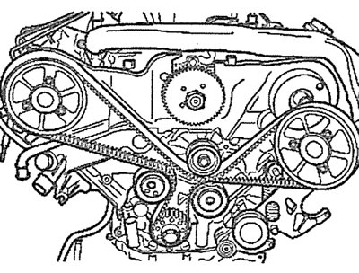
2.28. Timing belt installation direction
Attention! The final tightening of the bolts securing the camshaft gears to the hubs should not be performed at this stage. They should be tightened so that the gears can be turned, but they should not move axially on the hubs.
29. Turn the tension roller to the right using an 8 mm socket wrench (see arrow in illustration) so that it was possible to remove the T40011 pin, which secured the tensioner plunger.
2.29. Turn the tension roller to the right with an 8 mm socket wrench (see arrow) so that it was possible to remove the T40011 pin, which fixed the tensioner plunger
30. Tighten the toothed belt by turning the tension roller eccentric with a torque wrench applying a force of 15 Nm counterclockwise and in this position of the eccentric tighten the roller mounting bolt (see illustration).
2.30. Tension the toothed belt by turning the tension roller eccentric with a torque wrench applying a force of 15 Nm counterclockwise
31. Perform the final tightening of the camshaft gear mounting bolts, holding them from turning with the tool, catalog number 3036 (see illustration).
2.31. Perform the final tightening of the camshaft gear mounting bolts, holding them from turning with a device, catalog number 303S
32. Install in place and secure with bolts 1-4 (see illustration 2.20) fan mounting bracket with viscous coupling. Tightening torques: bolt 1-45 Nm, bolt 2-10 Nm, bolt 3-22 Nm, bolt 4-10 Nm.
33. Lock the fuel injection pump gear with a thrust roller, catalog number 3359, by inserting it into the hole on the gear and the corresponding hole on the cylinder block (see illustration). If there is no such thrust roller, then use a punch of suitable diameter and length.
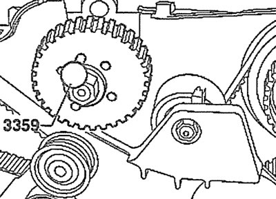
2.33. Lock the fuel injection pump gear with a thrust roller, catalog number 3359, by inserting it into the hole on the gear and the corresponding hole on the cylinder block
34. Install gear 1 of the fuel injection pump drive toothed belt on the camshaft of the left cylinder head and secure it with three bolts (see arrows in the illustration). Do not perform final tightening of the bolts at this stage.
2.34. Install gear 1 of the fuel injection pump drive toothed belt on the camshaft of the left cylinder head and secure it with three bolts (see arrows)
35. Turn the gear on the camshaft so that its mounting bolts are located in the center of their longitudinal holes.
36. Install the fuel injection pump drive toothed belt. If the previous belt was installed, observe its direction of travel.
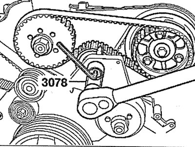
37. Turn the injection pump toothed belt tension roller counterclockwise until the arrows 1 are aligned. In this position of the roller, tighten its mounting bolt with an end insert, catalog number 3078 (see illustration).
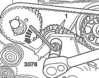
2.37. Turn the injection pump toothed belt tension roller counterclockwise until the arrows 1 align
38. Remove the locking devices that were used to lock the camshafts, the fuel injection pump drive gear and remove the locking pin 3242 that was used to lock the crankshaft (see illustration).
2.38. Remove locking pin 3242, which was used to lock the crankshaft
39. Turn the crankshaft in the direction of engine rotation and set the cylinder piston to TDC. Lock the crankshaft again by inserting the locking pin 3242 into the corresponding hole on the cylinder block (see illustration 2.38).
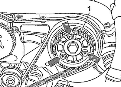
40. Make sure that the camshafts can be locked using the 3458 stoppers (see illustration). Otherwise, repeat the timing belt tension adjustment.
2.40. Make sure that the camshafts can be locked using stoppers 3458
41. Remove all locking devices used to lock the camshafts and crankshafts.
42. Make sure that the tension of the fuel injection pump drive toothed belt corresponds to the required one: arrows 1 and 2 of the tension roller must be aligned (see illustration).
2.42. Make sure that arrows 1 and 2 of the injection pump drive toothed belt tension roller are aligned
43. Install the vibration damper and the gears of the fuel injection pump drive toothed belt.
44. Install the V-belt pulley. The pulley locking tab should be positioned as shown in the illustration (see arrow).
2.44. The V-belt pulley locking tongue must be positioned as shown (see arrow)
45. Screw the plug into the hole on the cylinder block, into which the locking pin was installed to fix the crankshaft, after replacing the plug sealing ring with a new one. The tightening torque of the plug is 10 Nm.
46. Install the vacuum pump on the left cylinder head.
47. Install the camshaft covers (see arrow in illustration) on the right and left cylinder heads.
2.47. Install the camshaft covers (see arrow) on the right and left cylinder heads
Next, the installation of the dismantled components is carried out in the reverse order of removal.
(A link to the original source is available on the website audimanual.ru)