
Table of contents: Steering column switch block,… ↓ Removal and installation the… ↓ Removal and installation the… ↓ The location of the contacts of the… ↓ Removal and installation the "E2"… ↓ Removal and installation of the… ↓ Contact assignment of the access and… ↓
Steering wheel switch module. the column consists of a contact ring, a steering angle sensor "G85", and switches on the steering wheel. column (direction indicators, windshield wipers, cruise control system) and used steering electronics. columns "J527".
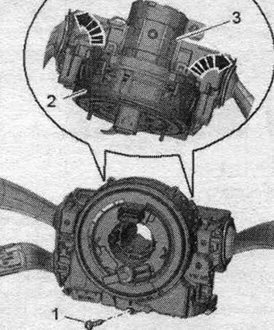
Steering column switch block, electronic ignition switch
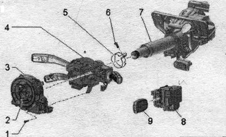
1. Bolt: 0.5 Nm.
2. Protection during transportation.
3. Used steering electronics. j527 columns: with an airbag coil spring and a return ring with a slip ring "F138", steering angle sensor "G85". Risk of damage to the return ring. It is prohibited to rotate the return ring with the contact ring when disassembled.
4. Mounting: with turn signal switch "E2", interval windshield wiper switch "E22": on vehicles with cruise control system (GRA) with switch for GRA "E45".
5. Retaining ring.
6. Bolt: 4 Nm.
7. Steering column.
8. Access and engine start switch "E415".
9. Ignition key.
Tightening torque for the access and engine start enable switch "E415"
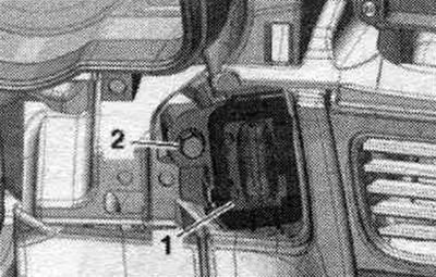
Tighten bolt "2" on the access and engine start enable switch "E415" "pos. 1" with a tightening torque of 3 Nm.
Removal and installation the steering column switch module
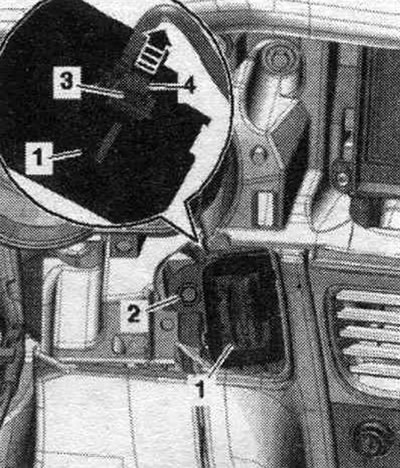
Set the steering wheel as far back and down as possible, using the full reg area for this. steering wheel position. speakers. Remove the driver's airbag. Remove the steering wheel. Remove the steering wheel cover. speakers. Unscrew bolt "1". Disconnect plug connection "2". Before disconnecting plug connector "3", the mechanic must be free of static electricity; for example, touching the door lock. Disconnect plug connection "3".
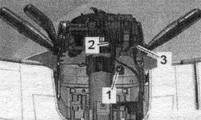
To do this, press the safety lock "1" in the "direction of the arrow" until the plug connection "2" is released. Carefully remove the steering wheel switch switch block. columns.
Installation in reverse order. Install steering wheel covers. speakers. Install the steering wheel. Install Airbag driver.
Removal and installation the steering column electronics control unit "J527"
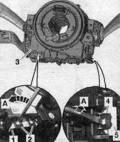
The used steering column "J527" has an integrated airbag coil spring, a return ring with a slip ring "F138" and a steering angle sensor "G85". When replacing a used one, select "Guided Fault Find" in the "Guided Fault Find" mode. or the Driven Functions function Replacement of the corresponding used one. Removal and installation of the return ring with the slip ring must be carried out in the middle position (wheels in straight-ahead position). Set the steering wheel as far back and down as possible, using the full reg area for this. steering wheel position. speakers. Remove the driver's airbag. Remove the steering wheel. Remove the steering wheel cover. columns. Unscrew bolt "1". Carefully unlock the "arrow" latch and remove the Airbag coil spring and return ring with contact ring "F138" "pos. 2" from the steering wheel switch switch block. column "3".
Unlock the plug connectors of the Airbag coil spring and the adjusting ring with the slip ring "F138" "pos. 3" by placing a screwdriver, as shown in the figure, on the locks "2" and "4" and carefully unlock the plug connectors "1" and "5" "in the direction of arrow A". Remove the Airbag coil spring and the return ring with the slip ring "F138" on the switch. steering wheel switch block. columns.
Installation in reverse order. Make sure all latches and connectors are securely fastened. Install steering wheel covers. speakers. Install the steering wheel. Install Airbag driver. After replacing the return ring with the contact ring, it is necessary to configure the steering angle sensor in the Guided Fault Search operating mode. or Slave functions.
The location of the contacts of the steering column electronics control unit "J527"
Used steering electronics. the "J527" column is part of the entire system. steering wheel switch module. column. It receives its signals, for example, from the steering column switch. Check used steering electronics. "J527" speakers in Guided Search mode are faulty.
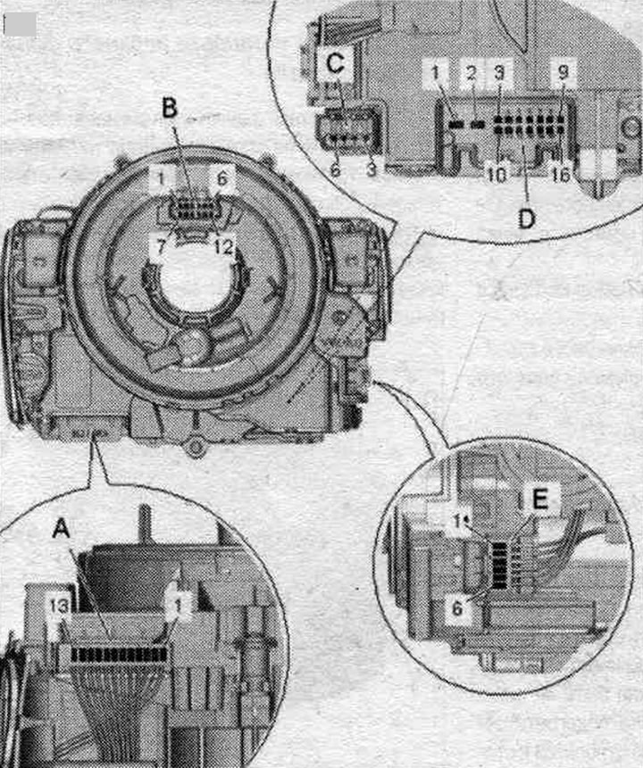
A. Turn signal switch/GRA connector
1. GRA lever weight.
2. GRA set.
3. ACC.
4. GRA Res (+)/Set (-).
5. Power supply (terminal 15).
6. GRA ground/direction indicator ground.
7. GRA Off.
8. GRA Res/Soft.
9. Radio (AIA).
10. Light signal.
11. High beam.
12. Direction indicator switch.
13. Switch mass. direction indicator.
B. Coil spring cassette/Airbag/Multi-function steering wheel/Horn socket
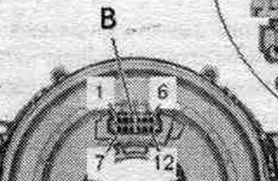
1. Mass.
2. Sound signal.
3. Airbag. 1 +.
4. Airbag. 1 -.
5. Airbag. 2 +.
6. Airbag. 2 -.
7. Press down.
8. Contact 30.
9. LIN.
10. Press up.
11. Dimming (terminal 58s).
12 Press. mass.
C. Plug connector of the airbag control unit
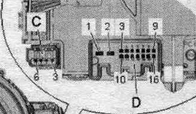
3. Airbag. 1 -.
4. Airbag. 1 +.
5. Airbag. 2 +.
6. Airbag. 2 -.
D. On-board electrical socket

1/2. Not involved.
3. Power supply, terminal 30.
4. CAN bus, drive shielding.
5. GRA latched, Off.
6. Not involved.
7. Radio/radio key.
8. CAN-bus Comfort Low.
9. CAN-bus Comfort High.
10. Power supply, terminal 31.
11. CAN-bus drive High.
12. CAN bus drive Low.
13. Electronic ignition switch signal, terminal 15.
14-16. Not involved.
E. Windscreen wiper/FIS connector
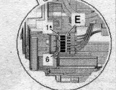
1. Weight of the windshield wiper.
2. Windscreen wiper switch.
3. Washing.
4. FIS signal.
5. Interval mode potentiometer.
6. Mass of information. driver's system (FIS).
Removal and installation the "E2" turn signal switches, the GRA "E45" cruise control, and the "E22" intermittent wiper
Removing the steering wheel switch switch block. speakers. Remove used steering wheel electronics. column "J527". Remove the turn signal switch "E2", the cruise control switch GRA "E45", the intermittent wiper switch "E22"
Installation in reverse order. Install used steering electronics. "J527" columns. Installation of the steering wheel switch junction box. columns.
Removal and installation of the access and engine start authorization switch "E415"
The immobilizer reading coil is fixed to the system switch. access and engine start authorization "E415" and cannot be replaced separately. If the reading coil is faulty, the system switch must be replaced. access and engine start authorization switch "E415". When replacing the access and engine start authorization switch, adaptation to the immobilizer is not required. The lock in the access and engine start authorization switch is not mechanically coded. Therefore, after replacing the switch. access and authorized engine starting keys do not need to be changed (the old keys will work). Remove the front cover. panels on the driver's side. Removing the MMI interface screen cover. Removing the instrument cluster slot trim. Unscrew bolt "2" of valve "1".
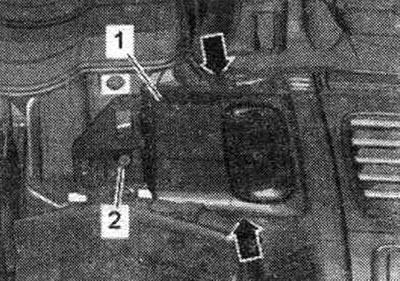
Insert the VAS 6339 ignition switch removal pliers through the throttle body covers. Insert the ends of the VAS 6339 ignition switch removal pliers into the "arrow A" holes of the "E415" access and start enable switch "2." Squeeze the VAS 6339 pliers together with "arrow B," which causes the ends to spread apart and release the throttle body retaining tabs. Hold "VAS 6339" in the pressed position with one hand, remove the flap "1" with the other hand "arrow C". To unlock, use the ignition lock removal pliers "VAS 6339", remove the flap by hand.
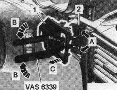
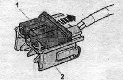
Unscrew the bolt "2". Remove the access and authorized engine start switch "E415" "pos. 1" by moving it forward into the driver's footwell, out of the front panel. Disconnect the connector "3"; to do this, slide the safety catch "4" upwards "arrow" and press the release lever inwards.
Installation in reverse order. Install the instrument cluster slot trim. Install the MMI screen cover. On US vehicles, install the right safety bar. Install the front cover. panels on the driver's side.
Contact assignment of the access and engine start authorization system switch "E415"
Nest
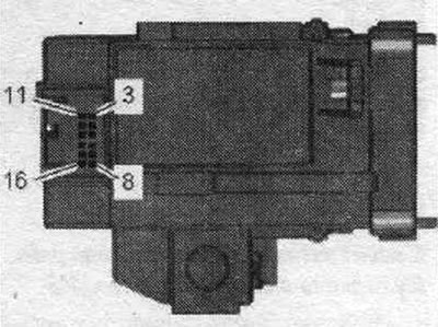
3/4. Not busy.
5. S-contact.
6. Terminal 15.
7. LIN.
8. Terminal 30.
9-12. Not busy.
13. RED2. terminal 15.
14. RED, terminal 15.
15. Ignition and starter switch +.
16. Terminal 31.