Repair Chevrolet Repair Toyota Repair Honda Repair AvtoVAZ Repair Mercedes-Benz Repair BMW Repair Opel
Home  |  Contacts  |  Sitemap  |    
English Русский
Български
Беларускі
Український
Српски
Hrvatski
Română
Polski
Slovenský
Magyar
AudiManual.ru


  • AUDI 80
  • AUDI 100
  • AUDI A3
  • AUDI A4
  • AUDI A6
  • AUDI A8
  • AUDI Q
  • OTHER
  • ARTICLES
B8 (2007-2015) B7 (2004-2008) B6 (2000-2006) B6 (2000-2006, petrol) B5 (1994-2001) B5 (1994-2001, petrol)

Engine Access and Start Authorization System — Component Overview (Audi A4 B8)

  • Home
  • Audi A4
  • B8 (2007-2015)
  • Electrical equipment
  • Equipment and devices
  • Engine Access and Start Authorization System — Component Overview
            0
Table of contents: Engine access and start… ↓ Keyless entry system components and… ↓ Keyless entry system exterior door… ↓ Removal and installation the front… ↓ Removal and installation the cabin… ↓ Removal and installation the antenna… ↓ Removal and installation the antenna… ↓

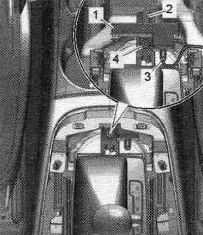
Engine access and start authorization system


1. Access and engine start switch «E415»; installation location: in the control panel, on the…

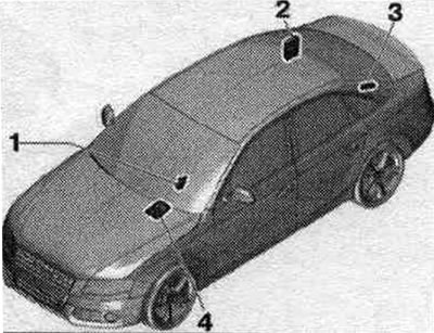
1. Access and engine start switch "E415"; installation location: in the control panel, on the driver's side.
2. Central used comfort system "J393": installation location: under the right side trim of the trunk.
3. Antenna for central locking and anti-theft alarm "R47": built into the rear window.
4. Used ELV (electromechanical steering shaft lock) "J764".


Keyless entry system components and components


1. Control button. right of access and engine start «E408»; installation location for MMI-Basis: in…

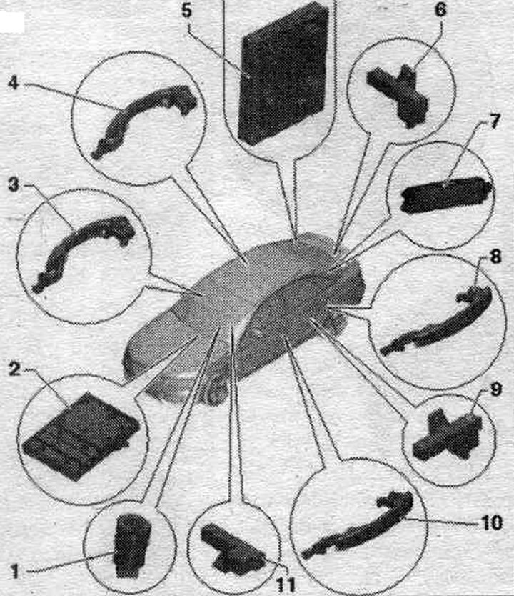
1. Control button. right of access and engine start "E408"; installation location for MMI-Basis: in the center trim, console; installation location for MMI-Comfort configuration: in the panel mounting frame. control, multimedia system. "E380".
2. Used ELV (electromechanical steering shaft lock) "J764".
3. External door handle on the front side. passenger: with a touch sensor on the outer handle of the front. right door "G606".
4. Outside door handle on the front side. passenger rear: with rear outer handle touch sensor. right door "G418".
5. Central used comfort system "J393": installation location: under the right side trim of the trunk.
6. Antenna system. access and engine start rights to the luggage compartment "R137"; installation location: on the left side of the rear panel. trunk walls.
7. Antenna for central locking and anti-theft alarm "R47": built into the rear window.
8. Outside door handle on the driver's side, rear: with rear outside handle touch sensor. left door "G417".
9. Antenna system. access control and engine start right, left "R200": installation location: on the rear left door.
10. Driver's door outside handle: with front outside handle touch sensor. left door "G605".
11. Cabin antenna 1 system. access rights and engine start "R138"; installation location: front, under the center, console.


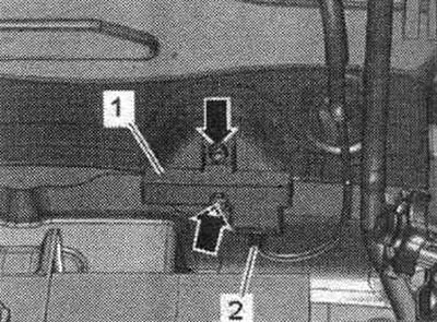
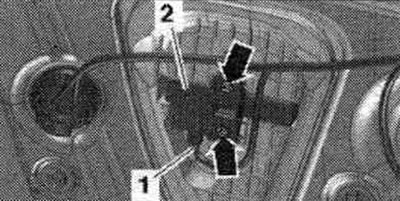
Tightening torque. Interior antenna 1 for the access and engine start authorization system "R138"


1. Cabin antenna 1 system. access rights and engine start «R138».

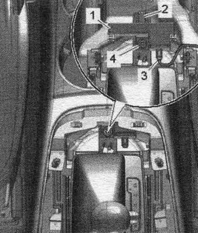
1. Cabin antenna 1 system. access rights and engine start "R138".
2. Fastening.
3. Electrical plug connection.
4. Bolt - 2 Nm.


Tightening torque. Left "R200" Access Control and Engine Starting System Antenna


Tighten the «arrow» bolts on the antenna system. access control and engine start right on the left…

Tighten the "arrow" bolts on the antenna system. access control and engine start right on the left "R200" with a torque of 2 Nm.


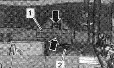
Tightening torque. Luggage compartment antenna for the access and engine start authorization system "R137"


Tighten the «arrow» nuts on the antenna in the luggage compartment of the system. access control…

Tighten the "arrow" nuts on the antenna in the luggage compartment of the system. access control and engine start right "R137" with a torque of 2 Nm.


Keyless entry system exterior door handle installation diagram


1. Outside door handle touch sensor: in the outside door handle; front door: front outer handle…

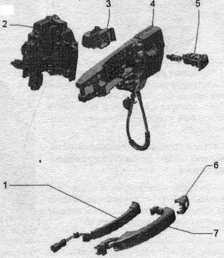
1. Outside door handle touch sensor: in the outside door handle; front door: front outer handle touch sensor. left door "G605", front outer handle touch sensor. right door "G606"; rear door: touch sensor in the outer rear handle. left door "G417", touch sensor in the outer rear handle. right door "G418".
2. Door lock.
3. Guide: lock switch.
4. Support bracket.
5. Lock cylinder: driver's side only.
6. Plug: driver side, for the lock cylinder, front side. passage, closed version.
7. Outside door handle.


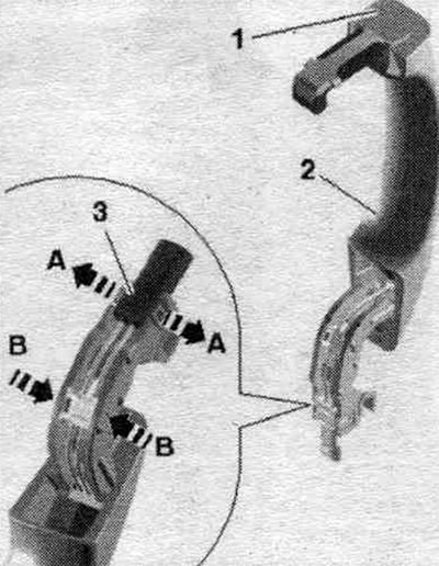
Removal and installation the front door outer handle touch sensor "G605"/"G606"


Remove the outside door handle. Unlock the "arrow A" latches and remove connector "3." Using a small screwdriver, carefully unlock the "arrow B" latches and remove the wiring harness. "Pos. 1, 2" do not take into account.

Remove the outside door handle. Unlock the «arrow A» latches and remove connector «3.» Using a…


Place a large, sturdy screwdriver on the outside door handle, as shown. Using firm force, push the outside door handle touch sensor forward from its retainer on the outside door handle. Remove the front outside door handle touch sensor from the outside door handle.


Place a large, sturdy screwdriver on the outside door handle, as shown. Using firm force, push the…


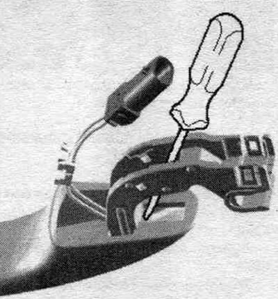
Installation in reverse order. Push the front outer handle touch sensor in until it locks into place audibly. Installing the external handle.

Removal and installation the cabin antenna 1 of the access and engine start authorization system "R138"


Cars with basic MMI-Comfort equipment: Remove the center console trim.

Cars with MMI-Comfort equipment: Removing the control panel, multimedia system. "E380".

All: Disconnect plug connection "3". Unscrew bolt "4". Remove internal antenna 1. Access and engine start authorization system "R138", "pos. 1".

All: Disconnect plug connection «3». Unscrew bolt «4». Remove internal antenna 1. Access and engine…


Installation in reverse order. When installing, ensure that antenna 1 in the cabin for the system. access control and engine start "R138" engaged with fastening "2".


Cars with basic MMI-Comfort equipment: Install the center console trim.

Cars with MMI-Comfort equipment: Installation of the panel. control, multimedia system. "E380".

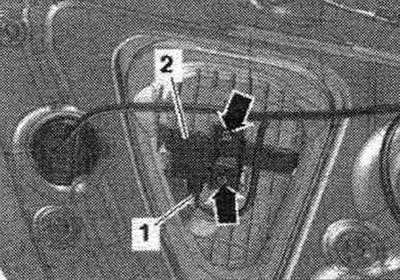
Removal and installation the antenna for the access control system and the right to start the engine on the left "R200"


Remove the rear trim. doors. Unscrew the "arrow" bolts and remove the left antenna of the system. access control and engine start "R200" "pos. 2". Disconnect plug connection "1".

Remove the rear trim. doors. Unscrew the «arrow» bolts and remove the left antenna of the system.…


Installation in reverse order. Install rear trim. doors.

Removal and installation the antenna for the access and engine starting system in the luggage compartment "R137"


Fold back the trunk bottom. Depending on the configuration, it is necessary to remove the side and tool mount. Avant: remove the spare wheel well trim. Unscrew the "arrow" nuts. Remove the system antenna. access control and engine start in luggage compartment "R137" "pos. 1". Disconnect plug connection "2".

Fold back the trunk bottom. Depending on the configuration, it is necessary to remove the side and…


Installation in reverse order. Avant: Install spare wheel well trim.

This publication is borrowed from the resource: AUDIMANUAL.RU
The article was checked by auto expert Timur Bazhenov
This article is available at russian, bulgarian, belarusian, ukrainian, serbian, croatian, romanian, polish, slovak, hungarian

Share information:
Previous articles
Audi A4 B8: Equipment and devices
Next articles

Interior Mirror Parts — Sensor Replacement
Parking assistant — overview of components
Steering column switch unit and electronic ignition switch
Washer reservoir, washer hose, headlight nozzle — removal and…
Ultrasonic interior security system — replacement of components
Lane Change Assist — Component Replacement
Towing hitch — replacement of components
Relay board, fuse box — replacement of components


Similar articles on other Audi car models:
Electrical diagram of the control unit of the fuel system of the… Audi 80 B4 (1991-1996)
Exhaust Gas Recirculation System — Information and Component… Audi 100 C3 (1982-1990, diesel)
Ignition switch and engine start Audi A3 Type 8L (1996-2003)
Diagnostics of engine cooling system faults Audi A6 C5 (1997-2004)
Central section of the cooling system pipe of a 2.5L diesel… Audi A8 D2 (1994-2002)
Access and engine start authorization system Audi Q5 Type 8R (2008-2017)
Towing to start the engine Audi A2 (1999-2005)
Link to this page in different formats


Visitor comments

No comments yet


How much will 22 + 28 =


A4(B8, 2007-2015) 
  • General information
  • Operating instructions
  • Power unit
  • Petrol engines 1.8 l
  • Petrol engines 1.8/2.0 l
  • Petrol engines 3.0 l
  • Petrol engines 3.2 l
  • Fuel system (petrol)
  • Diesel engines 2.0 l (CA*)
  • Diesel engines 2.0 l (CJCB)
  • Diesel engines 2.7/3.0 l
  • Diesel engines 3.0 l
  • Fuel system (diesel)
  • Transmission
  • Manual gearbox 0B1
  • Manual gearbox 0B2
  • Manual gearbox 0B3
  • Manual gearbox 0B4
  • Automatic transmission 0B5
  • Automatic transmission 0B6
  • Automatic transmission 0AW
  • All-wheel drive system
  • Chassis
  • Front suspension
  • Rear suspension
  • Brake system
  • Steering system
  • Body
  • Exterior
  • Interior
  • Seats
  • Doors, locks and windows
  • Security system
  • Heating and air conditioning
  • Electrical equipment
  • Audio system
  • Power devices
  • Equipment and devices
  • Lighting and lamps
  • Electrical circuits
 
A4(B7, 2004-2008) 
  • General information
  • Introduction to manual
  • Troubleshooting
  • Operating instructions
  • Maintenance
  • Power unit
  • Petrol engines 2.0 (ALT)
  • Petrol engines 2.0 (TFSI)
  • Petrol engines 1.8 (MPI)
  • Diesel engines
  • Cooling system
  • Air conditioner
  • Fuel and exhaust system
  • Ignition system
  • Starting and charging
  • Transmission
  • Clutch
  • Manual gearbox
  • Automatic gearbox
  • Drive shafts
  • Chassis
  • Brake system
  • Front suspension
  • Rear suspension
  • Steering
  • Body
  • Exterior
  • Interior
  • Electrical equipment
  • Equipment and devices
  • Lighting and signaling
  • Windscreen wipers and washers
  • Electrical diagrams
  • Electrical diagrams (since 2007)
 
A4(B6, 2000-2006) 
  • General information
  • Vehicle Description
  • User manual
  • Maintenance
  • Power unit
  • Gasoline engine
  • Diesel engine
  • Lubrication system
  • Cooling system
  • Supply system
  • Injection system
  • Exhaust system
  • Ignition and control
  • Transmission
  • Gear box
  • Clutch and drive shafts
  • Chassis
  • Brake system
  • Car suspension
  • Steering
  • Body
  • Heating and ventilation
  • Exterior (external elements)
  • Interior (internal elements)
  • Electrical equipment
  • Power devices
  • Lighting and appliances
  • Electrical circuits
 
A4(B6, 2000-2006, petrol) 
  • General information
  • Introduction to the guide
  • Car care
  • Power unit
  • Engine repair
  • Lubrication system
  • Cooling system
  • Injection and control system
  • Ignition system
  • Power and exhaust system
  • Transmission
  • Clutch and drive shafts
  • Car gearbox
  • Chassis
  • Suspension and wheels
  • Steering
  • Brake system
  • Body
  • Interior
  • Exterior
  • Electrical equipment
  • Equipment and devices
  • Lighting and signaling
  • Power devices
  • Electrical circuits
 
A4(B5, 1994-2001) 
  • General information
  • Introduction to the guide
  • Car care
  • Maintenance (gasoline)
  • Maintenance (diesel)
  • Power unit
  • Gasoline engines
  • Diesel engines
  • Engine overhaul
  • Cooling system
  • Fuel injection (gasoline)
  • Fuel system (diesel)
  • Exhaust system
  • Ignition system
  • Transmission
  • Clutch
  • Mechanical gearbox
  • Automatic gearbox
  • Drive shafts
  • Chassis
  • Brake system
  • Car suspension
  • Steering
  • Body
  • Exterior
  • Interior
  • Doors, locks and windows
  • Heating and ventilation
  • Electrical equipment
  • Power devices
  • Equipment and devices
  • Electrical circuits
 
A4(B5, 1994-2001, petrol) 
  • General information
  • Vehicle description
  • Maintenance
  • Power unit
  • Engine repair
  • Turbocharging
  • Exhaust system
  • Cooling system
  • Ignition system
  • Fuel system
  • Motronic injection system
  • MPI and MPFI injection system
  • Transmission
  • Clutch
  • Gearbox and shafts
  • Chassis
  • Steering
  • Car suspension
  • Brake system
  • Wheels and tires
  • Body
  • Heating and ventilation
  • Body parts
  • Electrical equipment
  • Fuses and relays
  • Power devices
  • Lighting and lamps
  • Tools and devices
  • Electrical circuits
 
AudiManual.ru © 2017-2026 · Mobile version · Feedback · Sitemap: EN BG BY UA RS HR RO PL SK HU · Site search · News and articles
80 B2 · 80 B3 petrol · 80 B3 · 80 B4 · 100 C3 diesel · 100 C3 petrol · 100 C3 · 100 C4 petrol · 100 C4 · A3 Type 8L · A4 B5 petrol · A4 B5 · A4 B6 petrol · A4 B6 · A4 B7 · A4 B8 · A6 C4 · A6 C5 · A6 C5 Allroad · A8 D2 · Q5 Type 8R · Q7 Typ 4L · Audi A2 ·
This site uses cookies 🍪. Click the button to accept this fact.