
Table of contents: Engine compartment junction box,… ↓ Removal and installation the… ↓ Removal and installation of the… ↓ Fuse box B "SB" in the engine… ↓ Engine compartment fuse box, removal… ↓ Removal and installation the 2nd… ↓ Removal and installation fuse box A… ↓
Engine compartment junction box, distributor, battery fuse box
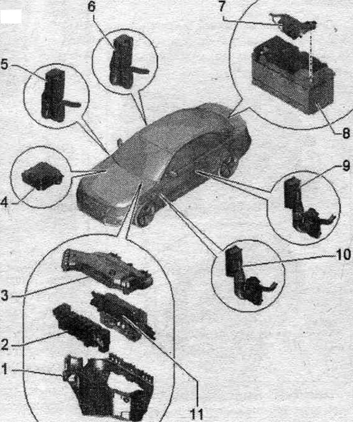
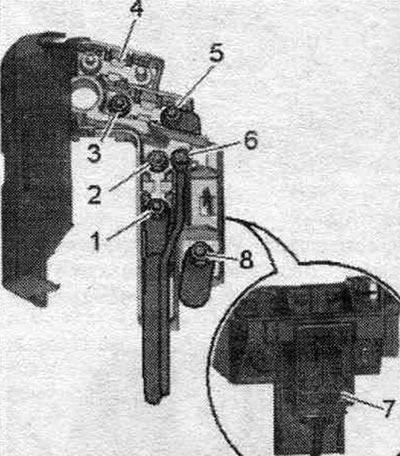
1. Switching unit mot. compartment.
2. Fuse box B "SB": relay box and fuse box in the switch. engine compartment block: with interference suppression capacitor "C24".
3. Facing of the switching unit in the motor. compartment.
4. Splitter 2 cl. 30 "TV22".
5. Front right door divider connector.
6. Rear right door divider connector.
7. Fuse box A "SA": in luggage compartment.
8. Battery.
9. Rear left door divider connector.
10. Front left door divider connector.
11. Used engine.
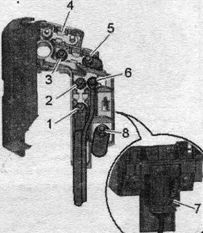
Tightening torque of the engine compartment junction box
1. Bolt, 3.5 Nm.
2. Cover for the switching unit motor. Compartment.
3. Bolt, 4.5 Nm.
4. Switching unit mot. compartment.
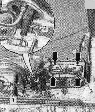
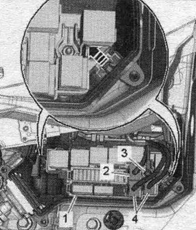
Tightening torque. Fuse box B "SB" in the engine compartment junction box
1. Positive wire, 9 Nm.
2. Fuse box B.
3. Electrical line on the back side, 9 Nm.
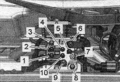
Tightening torque. Splitter 2 cl. 30 "TV22"
1/2. Fan wire, 7.5 Nm.
3. RTS wire, 18 Nm.
4. Nut, 7.5 Nm.
5. Positive wire of the switching block, 7.5 Nm.
6. Battery cable 16 Nm.
7. Connector for starting from an external power source "U6", 20 Nm.
8. Bolt, 7.5 Nm.
9. Positive starter wire, 18 Nm.
10. Nut. 7.5 Nm.
Tightening torque. Fuse box A "SA"
1. Electric wire, 7.5 Nm.
2/3. Nut, 9 Nm.
4. Fuse box A in the luggage compartment.
5. Positive wire to the engine, 7.5 Nm.
6. Bolt, 3.5 Nm.
7. Battery disconnector "N253".
8. Electric wire, 18 Nm.
Removal and installation the electrical box in the engine compartment
Disconnect the ground wire from the battery with the ignition off. Removing the filler neck for the windshield washer reservoir. Remove the windshield wiper motor. Unscrew the arrow bolts and remove the cover of the motorcycle switching unit. compartment. "Pos. 1" should not be taken into account.
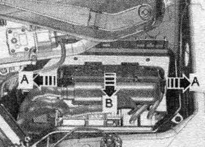
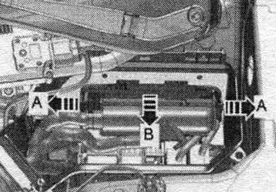
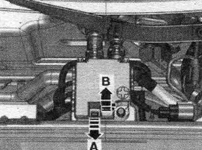
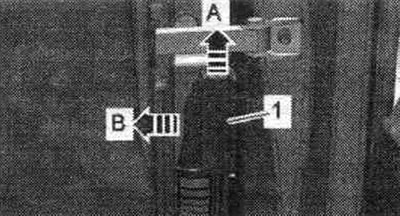
Unlock the "arrow A" clamps and remove the used "arrow B" engine.
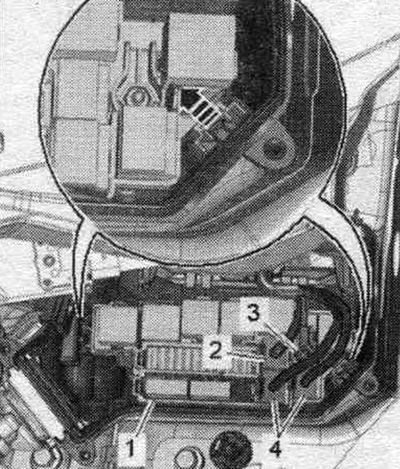
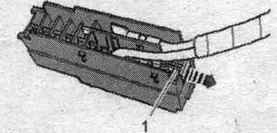
If present, disconnect connector "2". Disconnect connectors "4" and unscrew wire "3" on the front and rear sides. Unlock the "arrow" latches and remove fuse box B "pos. 1". Release and remove the engine wiring harness in the el. box.
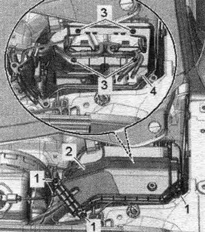
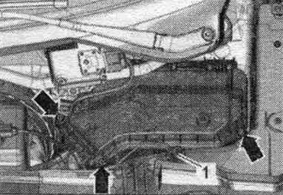
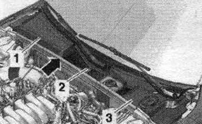
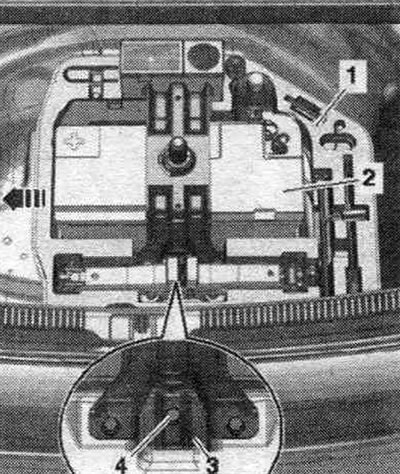
If available, remove the horn of the anti-theft alarm "H12" and freely lay the cable harness. Unscrew the "arrow" bolts, Disconnect the connector "1" for the brake pressure warning sensor. "F34" liquid. Lift the junction box in the engine. compartment "3" and disconnect connector "2" of the clutch pedal position sensor "G476".
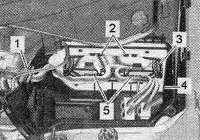
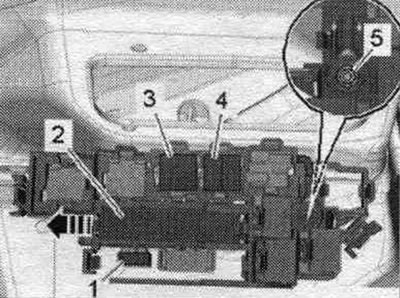
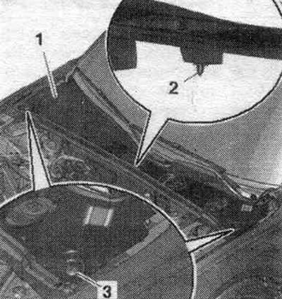
Remove the wiring harness "1" of the motorcycle switching unit. compartment. Unlock clamps "2" and "5" and push in the mounting frame "3" of the control units. engine as deep into the car interior as possible. Remove the engine junction box. compartment "4".
Installation in reverse order. Install fuse box B. Set the horn of the anti-theft alarm "H12". Connect the battery. Install the windshield wiper motor. Install the filler neck for the windshield washer reservoir.
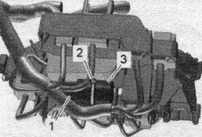
Removal and installation of the interference suppression capacitor "C24"
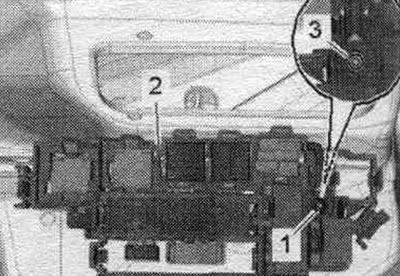
Remove the fuse box B of the junction box in the engine. compartment. Do not disconnect the connectors. Disconnect the binder "2". Disconnect the plug connection "1". Remove the radio interference suppression capacitor "C24" "pos. 3".
Installation in reverse order. Install fuse box B of the junction box in the engine. compartment.
Fuse box B "SB" in the engine compartment junction box, removal and installation
Disconnect the ground wire from the battery with the ignition off. Removing the filler neck for the windshield washer reservoir. Unscrew the arrow bolts and remove the cover of the motorcycle switching unit. compartment. "Pos. 1" should not be taken into account. Unlock the "arrow A" clamps and remove the used "arrow B" engine.
If present, disconnect connector "2". Disconnect connectors "4" and unscrew wire "3". Unlock the "arrow" latches and remove fuse box B "pos. 1". Release and remove the engine wiring harness in the el. box.
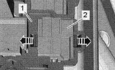
Unscrew the electrical line "5". Remove the relay "3" and control units. "4" from fuse box B. Unlock the "arrow" clamp, push fuse box "2" back and remove. Unlock the clamp and push back the add. fuse box "1".
Unlock the "arrow" clamps and push the relay block "2" back out of the holder "1". Remove the fuse block B from the engine junction box. compartment.
Installation in reverse order. Install the filler neck for the windshield washer reservoir. Connect the battery.
Engine compartment fuse box, removal and installation
Remove fuse box B. Unlock the "arrow" clamp, push fuse box "2" back and remove. Ignore the remaining positions. Unblock (if available) retainer and remove it from the fuse box. Remove the fuses from the block. Unlock the arrow latches and remove the fuse box cover.
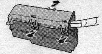
Remove the locking strips "1" of the "arrow" plug connections and remove the plug connections from the contact block.
Installation in reverse order. Install fuse box B. Connect the battery.
Removal and installation the 2nd class splitter 30 "TV22"
Vehicles manufactured before 05.2008: Unlock and remove the cover of the water drainage channel "2". Ignore "Pos. 1, 3" and "arrow".
For vehicles manufactured since 06.2008: Unscrew screws "3". Unfasten clips "2" from the mountings and remove the water drainage box cover "1".
All: Unlock the "arrow A" lock and remove the "arrow B" cover.
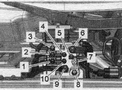
Unscrew the wires "1, 2, 3, 5, 6, 9". Unscrew bolt "8" and remove the 2nd class 30 "TV22" branch pipe from the tensioner. Ignore "Pos. 4, 7, 10".
Installation in reverse order.
Disconnecting the door divider connector
Unlock the plug retainer in the "direction of arrow A" and pull the door separating plug "1" outwards "arrow B".
Removal and installation fuse box A "SA" in the luggage compartment
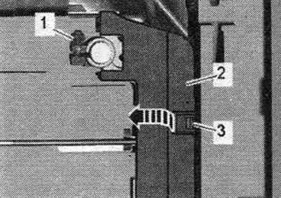
Disconnect the ground wire from the battery with the ignition off. Remove the "1" mount for the side tool. If present, remove the low-frequency speaker "1". If the fuse A cannot be removed from the battery terminal, unscrew the bolt "4" of the battery retaining bracket "3" and push the battery "2" out of the retainer slightly to the left "arrow".
Loosen the nut "1" a few turns and disconnect the positive cable terminal with the fuse block A from the battery pole. Unlock the spring retainer "3" and open the cover "2" over the fuse block A "arrow".
Unscrew the el. cables "1, 5, 6, 8". Disconnect terminal "4" of the positive wire from fuse block A from the battery terminal. Remove the battery disconnect switch "N253" "pos. 7". Remove fuse block A.
Installation in reverse order. Install the battery cut-off switch "N253". Install the mounting bracket. Connect the battery.