
Table of contents: Front Panel Fuse/Relay Box, A-Pillar… ↓ Removal and installation the fuse… ↓ Removal and installation the… ↓ Removal and installation a… ↓ Removal and installation the… ↓ Removal and installation the… ↓ Removal and installation the 6-pin… ↓ Removal and installation of the… ↓ Removal and installation of the… ↓ Removal and installation fuse box D… ↓ Removal and installation the 6-pin… ↓
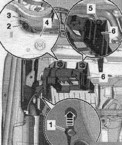
Front Panel Fuse/Relay Box, A-Pillar Fuse/Relay Box
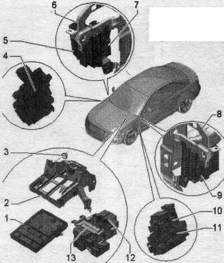
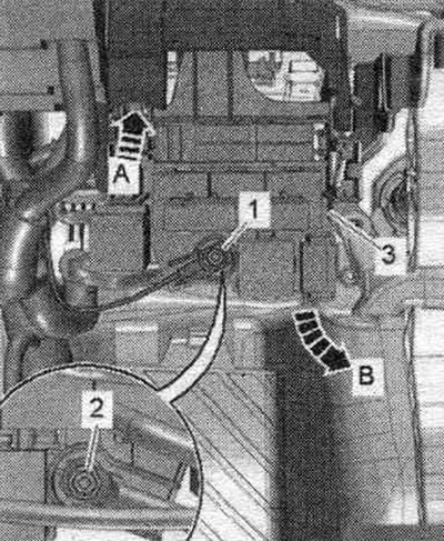
1. Used on-board network "J519".
2. Fastening for the relay and fuse box with used on-board network "J519".
3. Nut: 2 pcs.; 3 Nm.
4. 6-pin plug connector A post front side. passage.
5. Fuse box D "SD": on the right side of the instrument panel.
6. Central tube on the right.
7. CAN bus splitter connector, front panel. "T46s".
8. Central tube on the left.
9. Fuse box C "SC": on the left on the front. panels.
10. CAN bus splitter connector, passenger compartment. "T46i".
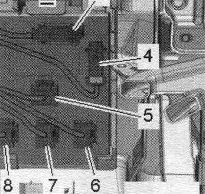
11. 6-pin connector block A pillar driver's side: left on front. panels.
12. Relay and fuse box with 3 positions: under the front panel on the left.
13. 4-position relay and fuse box with threaded connection: under the front panel on the left.
Tightening torques for 4-position relay and fuse box with threaded connection
1/2. Electric wire - 9 Nm.
3. 4-position relay and fuse box.
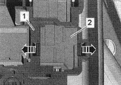
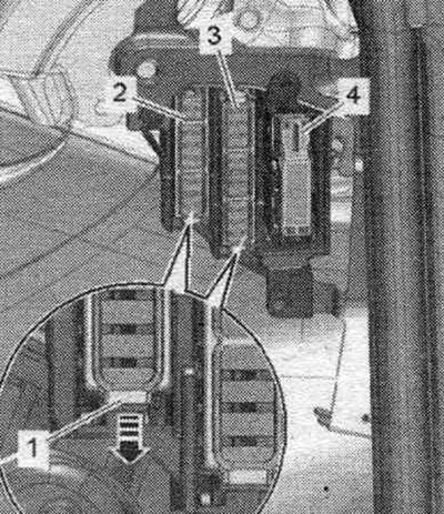
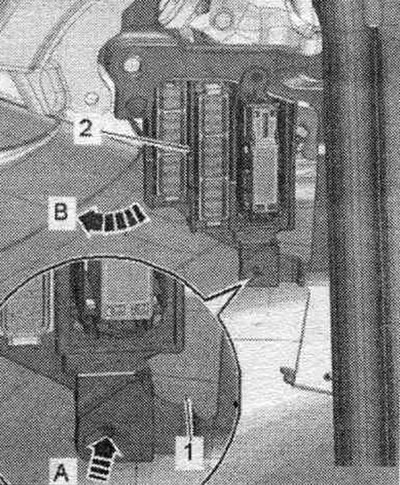
Removal and installation the fuse box C "SC" with fuse block, front panel left
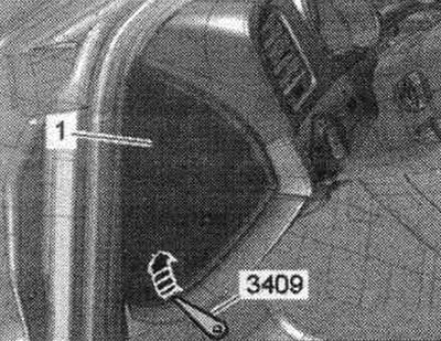
Lift the side trim "1" of the front panel with wedge "3409" "arrow" and remove.
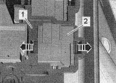
Unlock clamps "1" in the "direction of the arrow" and press fuse blocks "2...4" backwards from fuse block C.
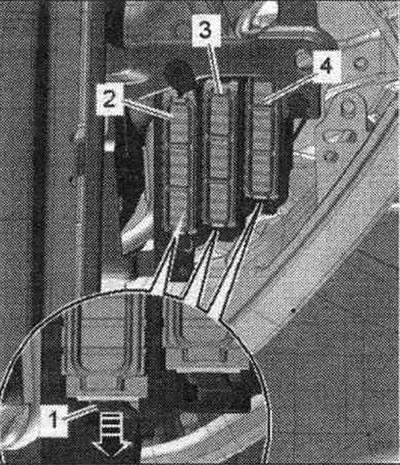
Unlock the clamp "arrow A" and remove the fuse block C "pos. 2" in the direction of arrow B - towards the center, pipe "1" front panel.
Installation in reverse order.
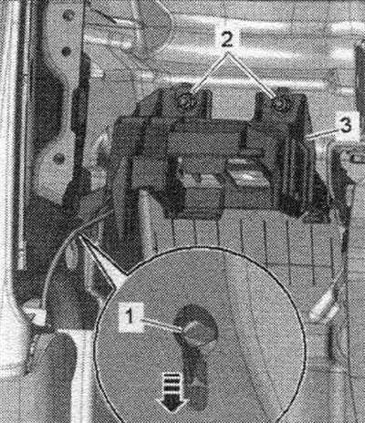
Removal and installation the 3-position relay and fuse box
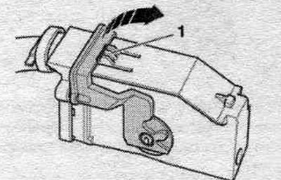
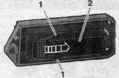
Turn off the ignition. Remove the front cover. driver's side dashboard. Remove the relay and fuse box by 3 positions. To do this, press the spring latches in the direction of the arrow and remove relay and fuse box "1". Disconnect the fuse blocks on the relay and fuse box.
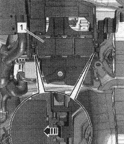
Remove the relay and control units. Unlock the "arrow" clamps and push relay unit "2" back out of holder "1".
Installation in reverse order. Install the front cover. panels on the driver's side..
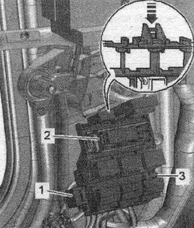
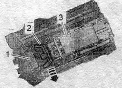
Removal and installation a 4-position relay and fuse box with a threaded connection
Turn off the ignition. Remove the front cover. panel on the driver's side. Remove the relay and fuse box by 3 positions. To do this, press the spring latches in the direction of the arrow and remove the relay and fuse box "1". Before unscrewing, mark the el. wires "1" and "2" for subsequent installation. Unscrew wire "1" on the 4-position fuse and relay box. Release the spring latch "arrow A" and remove relay and fuse box "3" from the mount "arrow B". On the rear side, unscrew wire "2" on the 4-position fuse and relay box. Disconnect the fuse box from the relay box.
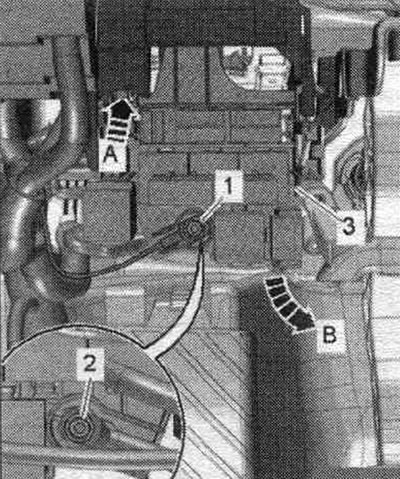
Remove the relay and control units. Unlock the "arrow" clamps and push relay unit "2" back out of holder "1".
Installation in reverse order. Install the front cover. panels on the driver's side..
Removal and installation the on-board power supply control unit "J519"
When replacing a used one, select the Guided search for faults mode. or the Guided Functions function Replace the corresponding used one. Turn off the ignition. Remove the front cover. driver's side dashboard. Remove the 3-position relay and fuse box. To do this, press the spring latches in the direction of the arrow and remove relay and fuse box "1". Unscrew wire "1" on the relay and fuse box in position 4. Release the spring latch "arrow A" and remove relay and fuse box "3" from the mount "arrow B". Ignore "Pos. 2".
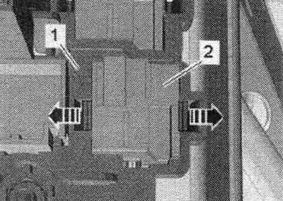
Unlock the spring latch "arrow" and remove the used on-board network "J519" "pos. 1" from the mount downwards. Disconnect the connectors "2, 5, 6, 7, 8". Disconnect plug connectors "3" and "4".
To disconnect the el. press the safety lock "1" of the connector, turn the fastening bracket in the "direction of the arrow" and remove the connector.
Installation in reverse order. Install the front cover. panels on the driver's side..
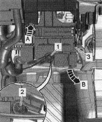
Removal and installation the fastening for the relay and fuse box with the on-board power supply control unit "J519"
Remove the left side front deflector. panels. Unscrew the "arrow" bolt of the air duct "1". The air duct cannot be removed.
Remove the used on-board network "J519." Push the socket head extension between the air duct "3" and the center tube "4" and remove the nut "2." To remove the nut "5," slide the socket head extension past the side of the mount "6," as shown in the figure. Remove the mount from the threaded studs. Unfasten the locking tab "1" of the fastening on the side guide of the A-pillar "arrow". To do this, fold the fastening towards the passenger compartment.
Installation in reverse order. Install bracket "1" of fastening "3" on the side guide of pillar A "arrow". Tighten nut "2".
Installing the air duct to the instrument panel deflector on the left. Remove the left side front deflector. panels.
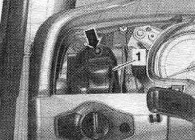
Removal and installation the 6-pin connector block A-pillar driver's side
Disconnect the ground wire from the battery with the ignition off. Remove the lower left A-pillar trim. Press the lock in the direction of the arrow and remove the connector block "3" on the A-pillar. Unclip the fuse blocks on the connector block. Disconnect connector "1".
Airbag. Remove fastener "2" for the CAN bus splitter connector in the T46i cabin.
Remove the relay and control units. Unlock the "arrow" clamps and push relay unit "2" back out of holder "1".
Installation in reverse order. Installing the CAN bus splitter bracket in the T46i cabin. Connect the airbag connector. Install the lower left A-pillar trim. Connect the battery.
Removal and installation of the interior CAN bus separating plug "T46i"
Turn off the ignition. Remove the lower left A-pillar trim. Press the latches "1" and release the safety clip "arrow". Remove the right CAN splitter connector, interior "T46i" "pos. 2".
Installation in reverse order. Install the lower left A-pillar trim.
Removal and installation of the interior CAN bus separating plug retainer "T46i"
Remove the left A-pillar plug block. Remove the interior CAN bus separating plug "T46i". Slide the safety lever "2" to the open position "arrow". Press the retainer "1" and push the retainer "3" for the interior CAN bus separating plug "T46i" backwards.
Installation in reverse order. Move the safety lever "1" on the mount to the closed position. Both arrow marks should be opposite each other.
Install the CAN bus splitter connector in the T46i interior. Install the left A-pillar connector.
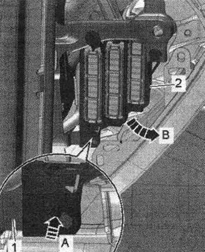
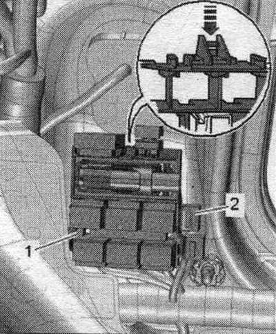
Removal and installation fuse box D "SD" with fuse box on the front panel on the right
Turn off the ignition. Remove the front compartment. Remove the CAN bus separator connector fastening, in the T46i passenger compartment, item 4. Unlock clamps 1 in the direction of the arrow and press fuse blocks 2 and 3 rearward from fuse block D.
Unlock the clamp "arrow A" and remove the fuse block D "pos. 2" in the "direction of arrow B" towards the center, pipe "1" of the front panel.
Installation in reverse order. Installing the CAN bus splitter connector mount in the T46i cabin. Install the front. box.
Removal and installation the 6-pin connector block A-pillar front passenger side
Disconnect the ground wire from the battery with the ignition off. Remove the trim of the right lower A-pillar. Press the lock in the direction of the arrow and remove the connector block "1" on the A-pillar. Unclip the fuse blocks "2" on the block. If present, disconnect Airbag connector "2".
Remove the relay and control units. Unlock the "arrow" clamps and push relay unit "2" back out of holder "1".
Installation in reverse order. Connect the airbag connector. Install the lower right A-pillar trim. Connect the battery.
[The text is based on materials from the website AUDIMANUAL.RU]