
Table of contents: Front Panel Relay and Fuse Block,… ↓ Tightening torque for the relay and… ↓ Tightening torques for 4-position… ↓ Removal the fuse block C "SC" with… ↓ Removal the relay block and fuse on… ↓ Installation ↓ Removal the relay and fuse block for… ↓ Installation ↓ Removal the used on-board network… ↓ Installation ↓ Removal the fastening for the relay… ↓ Installation ↓ Removal the 6-pin connector block… ↓ Removal the CAN bus splitter… ↓ Installation ↓ Removal the CAN bus splitter… ↓ Installation ↓ Removal the fuse block D "SD" with… ↓ Installation ↓ Removal the 6-pin connector block… ↓ Installation ↓
Front Panel Relay and Fuse Block, A-Pillar Relay and Fuse Block
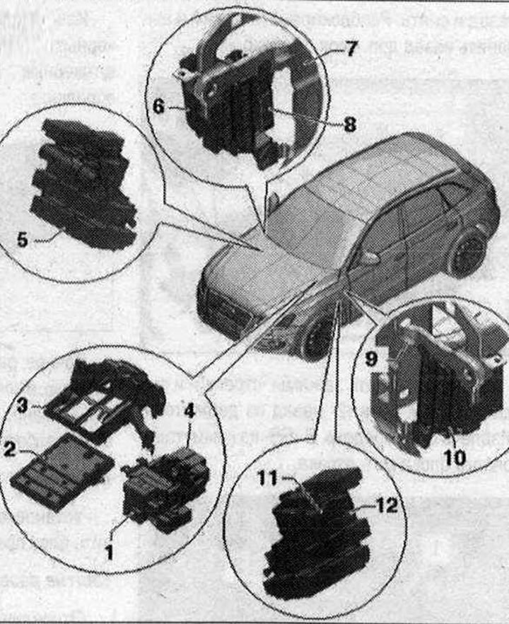
I 1. Relay and fuse block with 4 positions and threaded connection under the front panel on the left; 2. Used on-board network "J519"; 3. Fastening for the relay and fuse block with used on-board network "J519"; 4. Relay and fuse block for 3 positions under the front panel on the left; 5. 6-pin connector block A pillar front passenger side; 6. Fuse block D "SD" on the right side of the instrument panel; 7. Central tube on the right; 8. CAN bus splitter connector, front panel "T46s"; 9. Central tube on the left; 10. Fuse block C "SC" on the left side of the front panel; 11. CAN bus splitter connector, interior "T46i"; 12. 6-pin connector block A pillar driver's side left on the front panel
Tightening torque for the relay and fuse block.
Tightening torques for 4-position relay and fuse block with threaded connection
- 1. Email wire. 9 Nm
- 2. El. wire. 9 Nm
- 3. Relay and fuse block for 4 positions
Removal the fuse block C "SC" with fuse block, front panel on the left
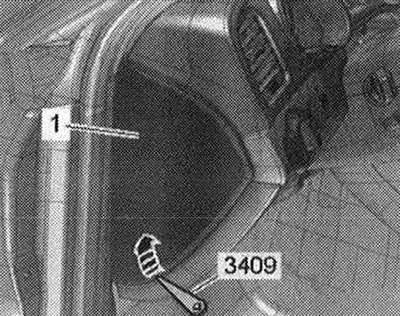
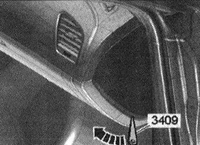
Disconnect the ground wire from the battery with the ignition off, vehicles with a high-voltage system. Lift the side trim "1" of the front panel with a wedge "3409" "arrow" and remove.
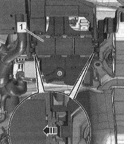
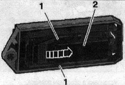
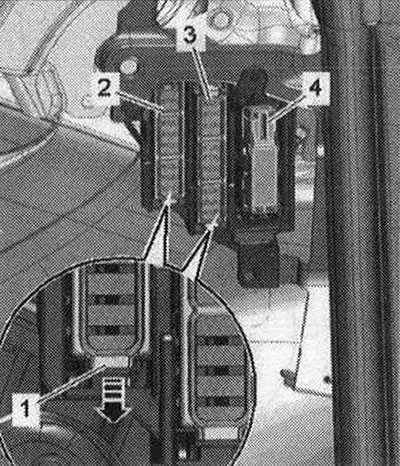
Unlock clamp "1" in the "direction of the arrow" and push fuse blocks "2...4" back out of fuse block C "SC".
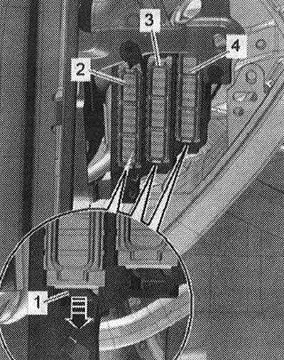
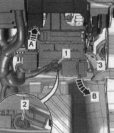
Unlock the clamp "arrow A" and remove the fuse block C -SC "pos. 2" in the direction of arrow B- on the central pipe "1" for the front panel.
Installation in reverse order.
Removal the relay block and fuse on 3 positions
Disconnect the ground wire from the battery with the ignition off, vehicles with a high-voltage system. Remove the storage compartment on the driver's side. Remove the relay and fuse block in position 3, to do this, press the spring latches in the "direction of the arrow" and remove the relay and fuse block. Disconnect the relay block from the relay and fuse block.
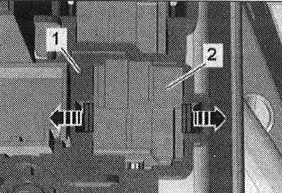
Remove the relays and control units. Unlock the "arrow" clamps and push the relay unit "2" back out of the holder "1".
Installation
Installation in reverse order: install the storage compartment on the driver's side.
Removal the relay and fuse block for 4 positions with a threaded connection
Disconnect the battery ground wire with the ignition off, vehicles with a high-voltage system. Remove the front panel cover on the driver's side. Remove the relay and fuse box at position 3 by pressing the spring latches in the "direction of the arrow" and removing the relay and fuse box "1". Before unscrewing, mark the electrical wires "1" and "2" for subsequent installation. Unscrew the electrical line "1". Unlock the spring latch "arrow A" and remove the relay and fuse box "3" from the mount "arrow B". On the rear side, unscrew the electrical wire "2" on the relay and fuse box at position 4. Disconnect the fuse box from the relay box.
Remove the relays and control units. Unlock the "arrow" clamps and push the relay unit "2" back out of the holder "1".
Installation
Installation in reverse order: install the storage compartment on the driver's side.
Removal the used on-board network "J519"
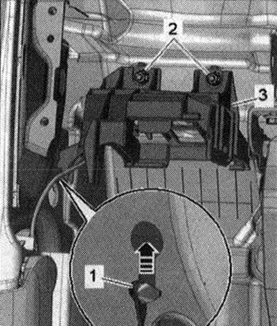
When replacing a used item, select the "Replace" function of the corresponding used item in the "Guided Fault Finding" or "Guided Functions" mode. Select the function or path: Vehicle brand - Engine code - 09 Electronic central switching unit J519 - 09 Replacement of used item. Follow further instructions on the diagnostic tester display. Switch off the ignition. Remove the front panel cover on the driver's side. Remove the relay and fuse box at position 3, to do this, press the spring latches in the "direction of the arrow" and remove the relay and fuse box "1".
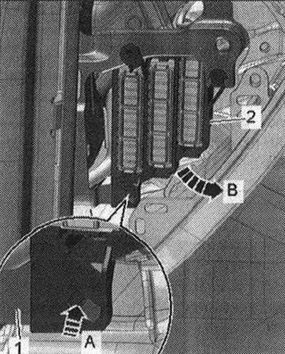
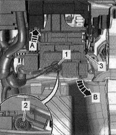
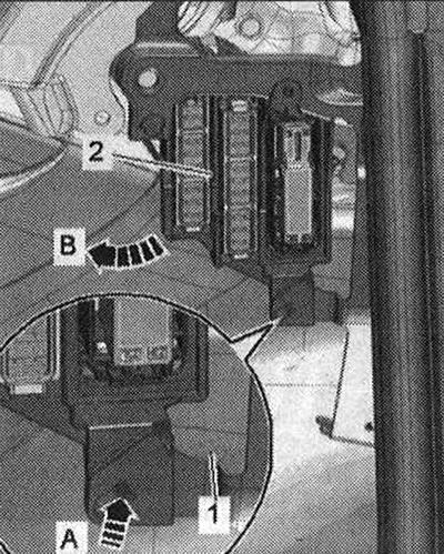
Unscrew the electrical line "1". Unlock the spring latch "arrow A" and remove the relay and fuse block "3" from the mount "arrow B".
"Pos. 2" do not take into account. Unlock the spring latch "arrow" and remove the on-board power supply control unit "J519" "pos. 1" downwards from the mount. Disconnect electrical connectors "2,5,6,7,8". Disconnect electrical connectors "3" and "4".
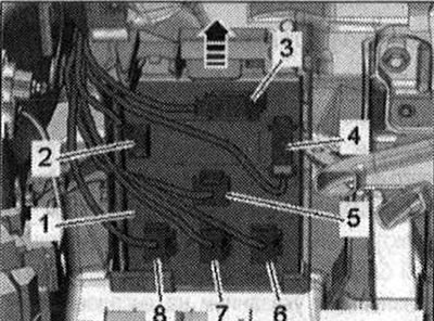
To disconnect the electrical connector, press the safety lock, turn the fastening bracket in the "direction of the arrow" and remove the connector.
Installation
Installation in reverse order: Install the dashboard cover on the driver's side. Follow the further instructions on the tester display for the new on-board power supply control unit "J519".
Removal the fastening for the relay and fuse block from a used on-board network "J519"
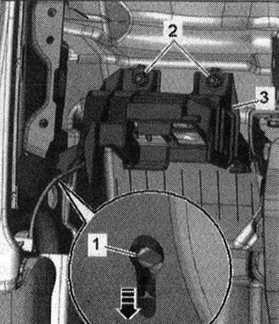
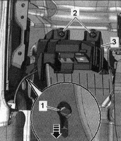
Disconnect the ground wire from the battery with the ignition off, vehicles with a high-voltage system. Remove the front panel. Remove the air duct to the instrument panel deflector on the left. Remove the on-board network control unit "J519". Unscrew the nuts "2". Pull the fastener "3" off the threaded studs. Remove the bracket "1" of the fastening on the side guide of the A-pillar "arrow", to do this, pull the fastener upwards.
Installation
Installation in reverse order: install bracket "1" of fastening "3" on the side guide of pillar A "arrow". Tighten nut "2".
Installing the air duct to the instrument panel deflector on the left. Install the front panel.
Removal the 6-pin connector block A-pillar driver side
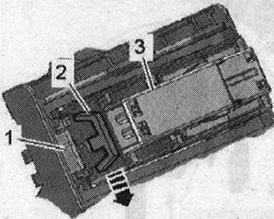
Disconnect the ground wire from the battery with the ignition off, vehicles with a high-voltage system. Remove the trim of the lower left pillar "A". Press the lock in the "direction of the arrow" and remove the plug connector "3" on the pillar A. Disconnect the fuse block from the connector. Disconnect the connector "1" Airbag. Remove the fastener "2" for the CAN bus separator connector in the passenger compartment of the "T46i".
Remove the relays and control units. Unlock the "arrow" clamps and push the relay unit "2" back out of the holder "1".
Installation in reverse order: installation of the mount for the CAN bus separator connector in the "T46i" passenger compartment. Disconnect connector "1" Airbag. Install the trim of the lower left A-pillar. Connect the battery.
Removal the CAN bus splitter connector, "T46i" interior
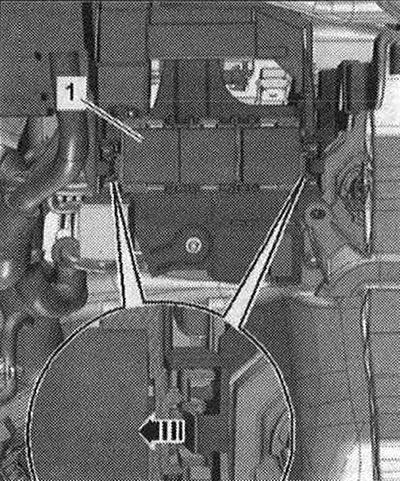
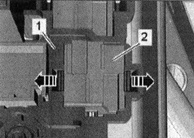
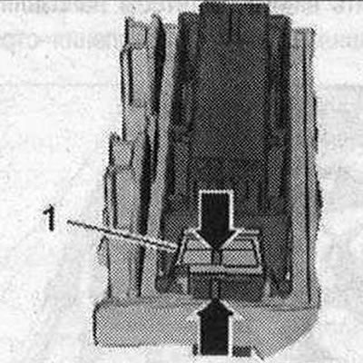
Switch off ignition. Remove lower left A-pillar trim. Press locks "1" and unlock safety clip "arrow". Remove right CAN-separator connector, interior "T461" "pos. 2".
Installation
Installation in reverse order: install the lower left A-pillar trim.
Removal the CAN bus splitter connector fastening, "T46i" interior
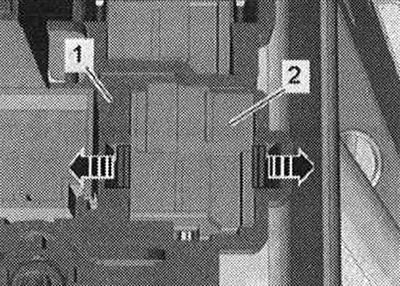
Switch off ignition. Remove left A-pillar connector. Remove CAN bus separator, in T46i passenger compartment. Move safety lever "2" to "open" position "arrow". Press lock "1" and push back fastening "3" for CAN bus separator, in T46i passenger compartment.
Installation
Installation in reverse order: move the safety lever "1" on the mount to the "closed" position. Both "arrow" marks must be opposite each other. Install the CAN bus separator connector in the "T46i" interior.
Install the left A-pillar connector.
Removal the fuse block D "SD" with the fuse block on the front panel on the right
Disconnect the ground wire from the battery with the ignition off, vehicles with a high-voltage system. Remove the glove box. Lift the side trim of the front panel with a wedge "3409" "arrow" and remove.
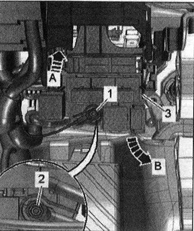
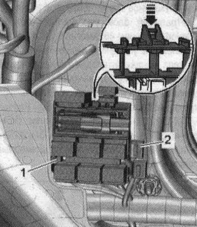
Remove the fastening for the CAN bus separator connector, instrument panel "T46s" "pos. 4". Unlock clamp "1" in the "direction of the arrow" and push fuse blocks "2" and "3" back out of fuse block D "SD".
Unlock the clamp "arrow A" and remove the fuse block D-SD "pos. 2" in the direction of arrow B- on the central pipe "1" for the front panel.
Installation
Installation in reverse order: Installing the bracket for the CAN bus splitter in the "T46s" instrument cluster. Install the glove box.
Removal the 6-pin connector block A-pillar front passenger side
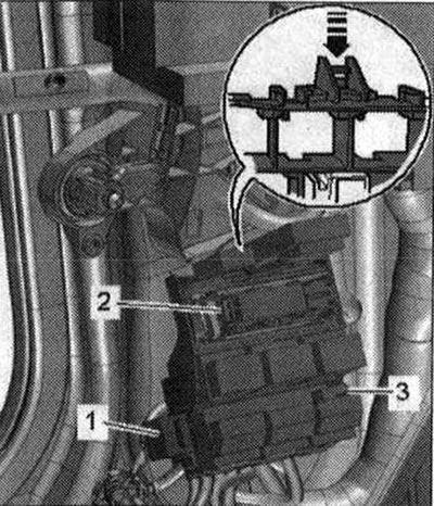
Disconnect the ground wire from the battery with the ignition off. Remove the trim of the right lower A-pillar. Press the lock in the "direction of the arrow" and remove the plug connector "1" on the A-pillar. Disconnect the fuse block "2" from the connector.
Remove the relays and control units. Unlock the "arrow" clamps and push the relay unit "2" back out of the holder "1".
Installation
Installation in reverse order: install the trim of the lower right A-pillar. Connect the battery.