
Table of contents: Washer reservoir, washer tubes,… ↓ Removal and installation the… ↓ Removal and installation of the… ↓ Removal and installation of the… ↓ Removal and installation injectors ↓
Washer reservoir, washer tubes, nozzle
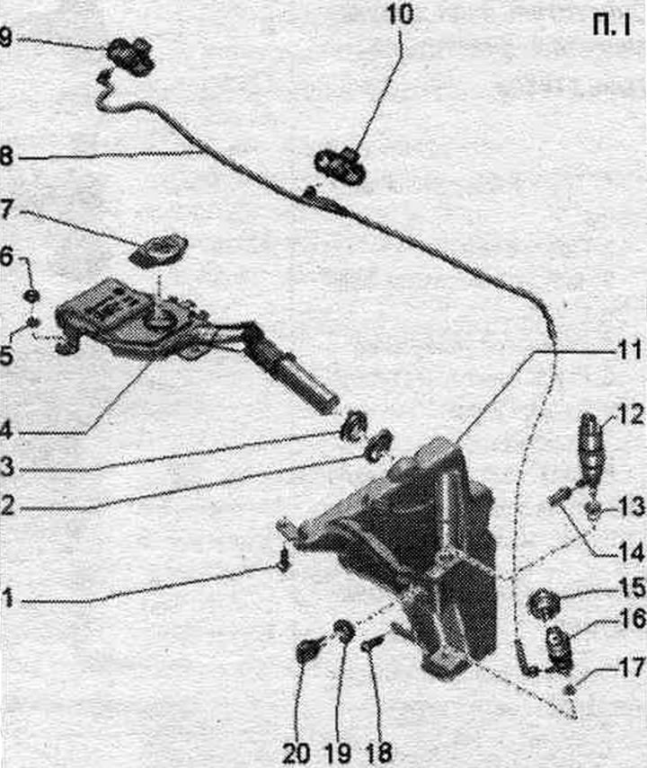
1/18. Bolt.
2. Sealing ring: replace if damaged.
3. Sealing bushing: replace if damaged.
4. Filler neck of the washer reservoir.
5. Support ring.
6. Nut: General threaded fastener with tension.
7. Lid: on the filler neck.
8. Washer pipe: for windshield washer.
9. Right injector: depending on the configuration with heating of the right injector "Z21".
10. Left injector: depending on the configuration with heating of the left injector "Z20".
11. Washer reservoir.
12. Headlight washer pump "V11".
13/17/19. Sealing sleeve.
14. Headlight washer tube.
15. Fastening ring: for windshield washer pump -V5.
16. Windscreen washer pump "V5".
20. Windshield washer fluid level sensor "633".
Windshield washer reservoir - torque and tightening sequence
Tighten the windshield washer reservoir bolts in the specified order:
1. Tighten bolt -3/4- to 7 Nm.
Removal and installation the windshield washer reservoir
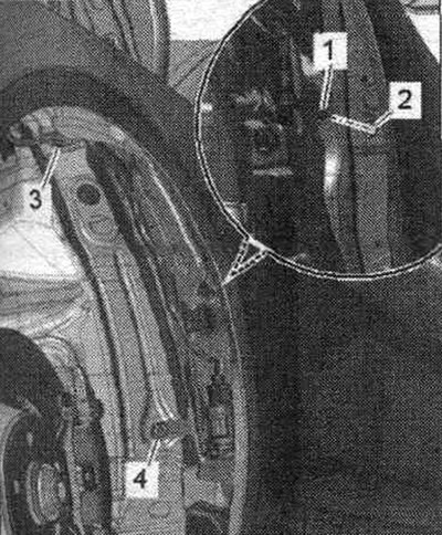
Turn off the ignition. Removing the filler neck for the windshield washer reservoir. Remove the front left wheel. Remove the front left fender liner. Place a collecting container under the washer reservoir. Pull the hose coupling "1" off the water hose "3" for the headlight washer, and pull the release button to do this. Cut binders "2" and "4". Remove plastic wedge "5".
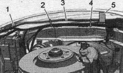
Disconnect plug connectors "7" and "8". Unlock the safety clip and disconnect the washer tubes from the washer water pump "9". Remove the wiring harness "2" from the fasteners on the windshield washer reservoir. Unscrew bolts "1" and "3". Pull the windshield washer reservoir forward slightly. Disconnect plug connection "5". Remove headlight washer water hose "6" and wiring harness "4" from the fasteners on the windshield washer reservoir. Remove the windshield washer reservoir.
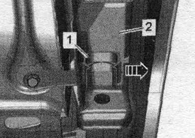
Installation
When installing the washer reservoir, ensure that retainer "1" fits into recess "2" on the fender. Installation is in reverse order. Install the front left fender liner. Install the filler neck for the windshield washer reservoir.
Removal and installation of the washer fluid level sensor "G33"
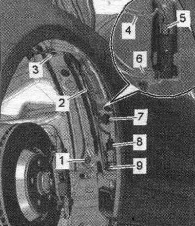
Turn off the ignition. Remove the front left wheel. Remove the front left fender liner. Disconnect plug connection "1". Place a collecting container under the washer reservoir. Remove the windshield washer fluid level sensor "G33" "pos. 3" from the windshield washer reservoir "4".
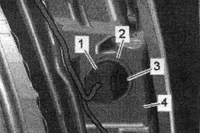
Installation in reverse order. Check the seal. bushing "2" for damage. Install the front left fender liner.
Removal and installation of the washer fluid pump "V5"
Turn off the ignition. Remove the front left wheel. Remove the front left fender liner. Disconnect plug connection "4". Place a collecting container under the washer reservoir. Unlock the safety clip "2" in the "direction of the arrow" and disconnect the washer pipe "1" from the windshield washer nozzle. Remove the windshield washer pump "V5" "pos. 3" upwards from the windshield washer reservoir.
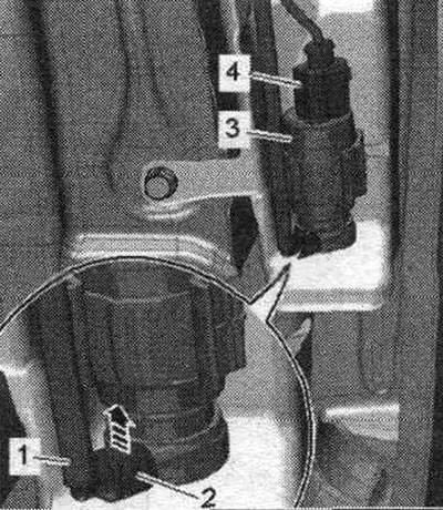
If the holder for the windshield washer pump "V5" is damaged, then it is necessary to replace the holder. Use a screwdriver to push the damaged holder "1" out of the mount in the windshield washer reservoir "2" to the outside of the Strelka car.
Installation in reverse order. Check the seal. bushing for damage. Install the front left fender liner.
Removal and installation injectors
Disconnect the washer nozzles "1" from the bottom of the front. "arrow" flaps.
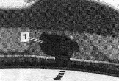
Unlock the safety clip "3" "in the direction of the arrow" and disconnect the washer pipe "2" from the windshield washer nozzle. If present, disconnect plug connection "1".
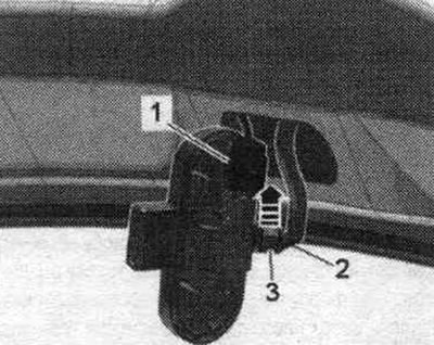
Installation in reverse order. When installing the washer tube, ensure that the safety clip snaps into place with a clearly audible click into the washer tube connection. Install the nozzle into the hood.