



Table of contents: Data bus diagnostic interface ↓ Removal and installation the… ↓ Connector in the diagnostic… ↓ Multi-pin plug connection, 20-pin… ↓
Data bus diagnostic interface
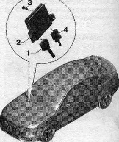
1. Electrical plug connection: diagnostic data bus interface "J533".
2. Diagnostic interface of data bus "J533".
3. Bolt: 3 Nm.
4. Optical cable plug connection: Cover with a protective cap for cable connectors "VAS 6223/9".
Removal and installation the diagnostic data bus connector "J533"
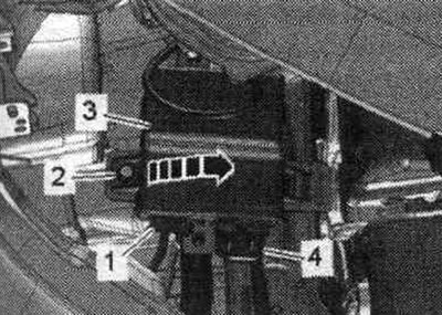
When replacing a used one, select the Guided search for faults mode. or the Guided Functions function Replace the corresponding used one. Turn off the ignition. Remove the front drawer. Unscrew bolt "2". Remove the diagnostic. data bus interface "J533" "pos., 3" from the holder "arrow". Disconnect plug connection "4". Disconnect connector "1" of the fiber optic line.
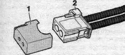
Cover the open connector of the optical cable harness "2" with a protective cap "VAS 6223/9" "pos. 1". The protective cap prevents contamination or mechanical damage to the end surface of the optical cable, which would otherwise impair optical transmission.
Installation
Installation in reverse order. Set per. box. Follow the further instructions on the tester display with the new data bus diagnostic interface "J533".
Connector in the diagnostic interface of the data bus "J533"
Connecting the MOST optical bus (optical cable) "pos. A"
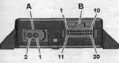
1. Entrance.
2. Exit.
Multi-pin plug connection, 20-pin "pos. B"
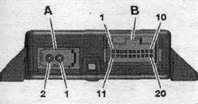
1. Battery + (terminal 30).
2. LIN 1.
3. Screen (ACC-ReL).
4. Screen (ELV).
5. CAN bus Low (comfort).
6. CAN bus Low (drive).
7. CAN bus Low (extended).
8. CAN bus Low (combi).
9. CAN bus Low (diagnostics).
10. Screen (mOST bus diagnostics).
11. Ground (terminal 31).
12. LIN 2.
13. Wake-up signal of the instrument cluster.
14. Terminal 15.
15. CAN bus High (comfort).
16. CAN bus High (drive).
17. CAN High bus (Extended).
18. CAN bus High (combi).
19. CAN bus High (diagnostics).
20. Screen.
[A link to the original source is available on the website AudiManual.ru]