



Table of contents: Instrument cluster ↓ Removal and installation the… ↓ Pin assignment in the multi-pin plug… ↓ Removal and installation the G17… ↓ Removal and installation the G17… ↓ Removal and installation of the… ↓
Instrument cluster
Note: All indicator lamps in the instrument cluster are equipped with LEDs. If one alarm fails, the used instrument cluster must be replaced.
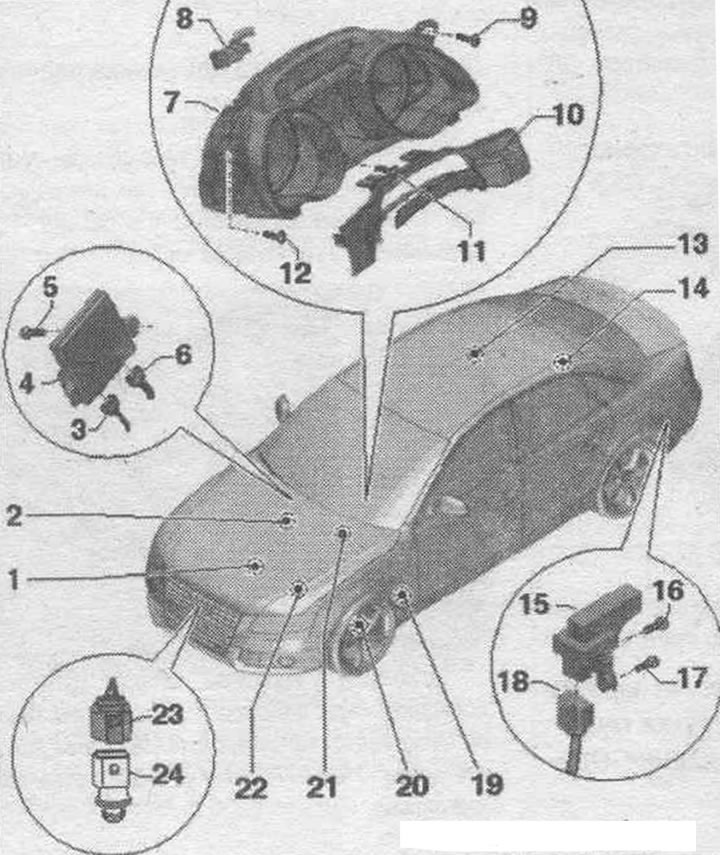
1. Oil level and temperature sensor "G266".
2. Oil pressure sensor "F1".
3. Electrical plug connection diagnostic. data bus interface "J533".
4. Diagnostic interface of data bus "J533".
5. Bolt.
6. Optical cable plug connection: Cover with a protective cap for cable connectors "VAS 6223/9".
7. Instrument cluster: with used instrument cluster "J285"; assignment of contacts in a multi-pin plug connection.
8. Electrical plug connection: for instrument cluster.
9. Bolt: 2.5 Nm.
10. Slotted overlay.
11/12. Bolt: 2.5 Nm.
13. Fuel level sensor "G".
14. Fuel level indicator sensor 2 "G169".
15. Radio clock receiver "J489".
16/17. Bolt: 2.5 Nm.
18. Electrical plug connection: for radio clock receiver "J489".
19. Windshield washer fluid level sensor "G33".
20. Brake wear sensor. linings: front left "G34".
21. Low brake pressure warning contact. liquids "F34".
22. Low coolant level indicator sensor "F66".
23. Electrical plug connection: outside air temperature sensor "G17".
24. Outside air temperature sensor "G17".
Removal and installation the instrument cluster with the instrument cluster control unit "J285"
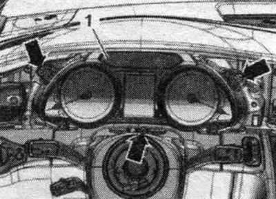
It is prohibited to disassemble used instrument clusters. To remove the instrument cluster, it is not necessary to remove the steering wheel. If you are replacing the instrument cluster with a used instrument cluster "J285", then select the Guided Fault Search operating mode. or the Driven Functions function. Replace the corresponding used one. Set the steering wheel as far back and down as possible, using the full adjustment area. steering wheel position. speakers. Turn off the ignition. Remove the butt plate. Remove the joint cover from the upper part of the steering wheel. columns. Cars up to model year 2012: Remove the left front deflector. mMI instrument cluster and screen trim. Cars from 2013 model year: Remove the MMI screen trim. Unscrew the "arrow" bolts. Move the instrument cluster "1" until it is flush with the steering wheel. Disconnect the plug connection.
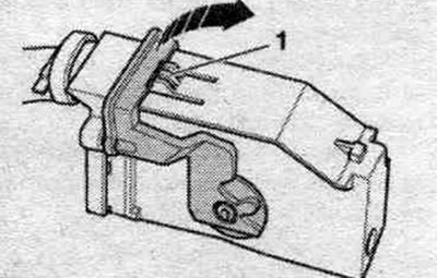
To disconnect the el. press the locking button "1" of the plug connection, turn the locking bracket in the "direction of the arrow" and disconnect the plug connection. Remove the instrument cluster located between the steering wheel and the control panel towards the driver's side.
Installation in reverse order. Follow further instructions on the diagnostic display. tester with a new instrument cluster.
Pin assignment in the multi-pin plug connector in the instrument cluster
32-pin connector, gray
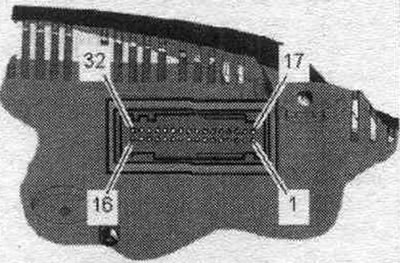
1. Not busy.
2. CAN bus wake-up wire, screen.
3. CAN bus wake-up wire, Low.
4. CAN bus wake-up wire, High.
5. Ground wire of fuel level sensor "G", contact 2.
6. Fuel level sensor "G", contact 4.
7. Fuel level sensor "G", contact 3.
8. Key module.
9. Fuel level sensor 2 "G169", contact 2.
10. Fuel level sensor 2 "G169", contact 1.
11-19. Not busy.
20. Control probe.
21/22. Not busy.
23. Radio clock 5 V.
24. Radio clock signal.
25. Oil level.
26-28. Not busy.
29/30. Terminal 31.
31/32. Terminal 30.
Connection diagram for the fuel level indicator sensor "G"
Disconnect el. 5-pin connection from a blind fuel flange. tank.
5-pin fuel level sensor "G" connector pinout
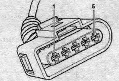
1. Positive terminal of fuel pre-supply pump "G6".
2. Cable from the fuel level indicator sensor "G" to the instrument cluster (sensor ground cable) - contact 5.
3. Cable from the fuel level indicator sensor "G" to the instrument cluster (indication of the fuel level in the fuel tank. tank) - contact 7.
4. Cable from the fuel level indicator sensor "G" to the instrument cluster (indication of the fuel level in the fuel tank. tank) - contact 6.
5. Ground for fuel pre-supply pump "G6". For vehicles with FSI and TFSI engines, contacts "2, 3, 4" use the used fuel pump "J538".
Connection diagram for fuel level indicator sensor 2 "G169"
Disconnect el. 2-pin plug connection from blind flange fuel. tank.
Pin assignment of the 2-pin connector of the 2nd fuel level sensor "G169"
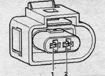
1. Cable from fuel level sensor 2 "G169" to the instrument cluster (sensor ground cable) -contact 10.
2. Cable from fuel level sensor 2 "G169" to the instrument cluster (fuel tank level indicator) - contact 9.
Assignment of temperature sensor connector contacts. Coolant "G62" - FSI engines
Disconnect the 2-pin plug connection from the temperature sensor. OZ "G62"; the sensor cannot be removed.
Layout of the 2-pin plug connector on the temperature sensor. OZ "G62"
1. Sensor mass.
2. Cable connection coming from the temperature sensor. Coolant "G62" to the control unit. engine.
Assignment of contacts for coolant level sensor connectors "G62"/"G83" - TDI engines
Disconnect the 2-pin plug connection from the temperature sensor. OZ "G62"; the sensor cannot be removed. Disconnect the 2-pin connector from the temperature sensor. Coolant at the radiator outlet "G83"; the sensor cannot be removed.
Layout of the 2-pin plug connector on the temperature sensor. OZ "G62"
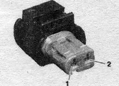
1. Sensor mass.
2. Cable connection coming from the temperature sensor. Coolant "G62" to the control unit. engine.
Distribution of electrical charges of the 2-pin connector of the coolant temperature sensor at the outlet of the cooling system "G83"
1. Sensor mass.
2. Cable connection from the temperature sensor. Coolant at the system outlet. cooling "G83" to the control unit. engine.
Removal and installation the G17 outside temperature sensor - vehicles up to model year 2012
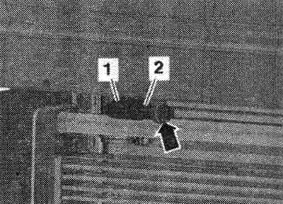
Remove the lock support trim. Disconnect plug connection "1". Carefully squeeze the "arrow" latches and pull out the outside temperature sensor. "G17" "pos. 2" from the fastening upwards.
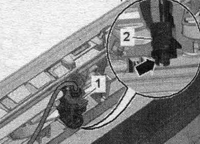
Installation in reverse order. Install the lock support trim.
Removal and installation the G17 outside temperature sensor - vehicles from the 2013 model year
Remove the lock support trim. Carefully squeeze the "arrow" clamps and remove the outside air temperature sensor "G17" "pos. 2" from the mount. Disconnect plug connection "1". The figure shows this operation with the bumper cover removed.
Installation in reverse order: install the lock support trim.
Removal and installation of the radio clock receiver "J489"
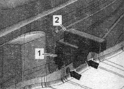
Remove the rear trim. bumper. Unscrew the "arrow" bolts and remove the radio clock receiver - J489- "pos. 2". Disconnect connector "1" on the radio clock receiver "J489".
Installation in reverse order: install the rear trim. bumper. If the bumper cover was removed, then the lane change assist system is used "J7697"/"J770" must be recalibrated.
[The article was copied from the website «AudiManual»]