
1. Guided by Chapter 3, paragraph 2, disconnect the negative battery cable.
2. Remove the steering wheel (Section 10).
3. Using a screwdriver inserted through the hole in the base of the combination switch/speaker cover, loosen the bracket, then lift the unit up.
4. Remove the instrument panel (Chapter 15).
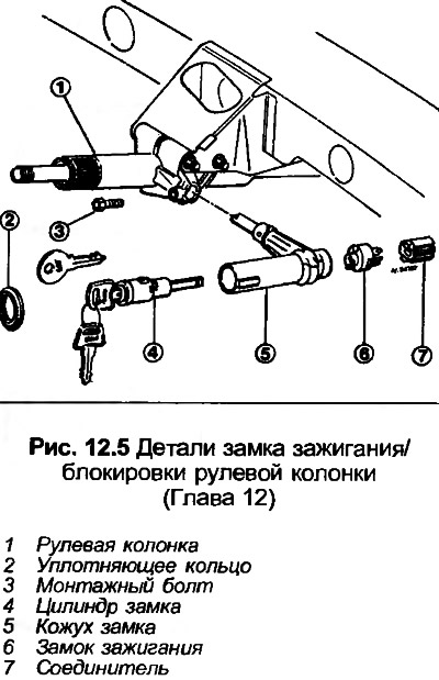
5. Unscrew the bolt securing the lock casing to the column.
6. Loosen and remove the two upper column mounting bolts, then the lower one, remove the lock housing. Disconnect the wiring.
7. Clean the paint off the screws, then unscrew them and pull out the ignition switch.
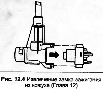
8. To remove the lock cylinder, you will need to drill a 3 mm diameter hole in the casing at the location shown in Fig. 12.6, 1.5 mm deep. Using a screwdriver inserted into the hole, press the fastening button and remove the lock cylinder.
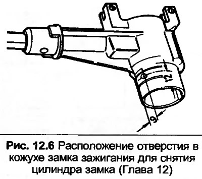
9. Installation is done in the reverse order. When installing the ignition switch, insert the key into the cylinder and turn it fully counterclockwise. Insert the switch into the casing, tighten the screws and lock them with paint. Make sure that the lower steering column coupling is inserted correctly, if necessary, see Section 10.
The original source of the article can be found on the website AUDImanual.ru