
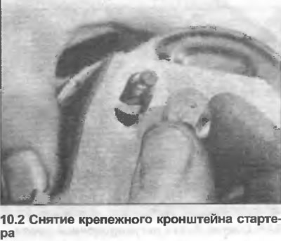
2. Remove the nuts and washers, take out the mounting bracket (photo).
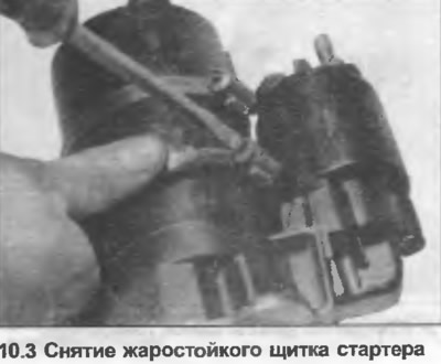
3. Loosen the clamps and remove the heat-resistant shield (where is it used) (photo).
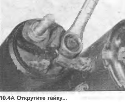
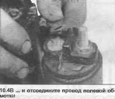
4. Unscrew the nut, disconnect the field winding wire from the solenoid clamp (photo).
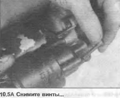
5. Unscrew the screws, disconnect the traction relay from the drive casing (photo).
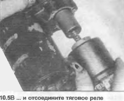
6. Disconnect the traction relay core from the engagement lever (photo). Remove the spring if necessary.

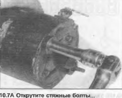
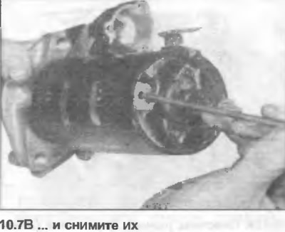
7. Unscrew the tie bolts and remove them from the bearing housing (photo).
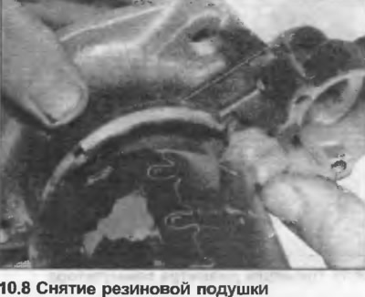
8. Remove the rubber pads from the engagement lever (photo).
9. Disconnect the drive casing from the yoke and remove it from the engagement lever.
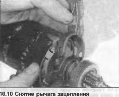
10. Disconnect the engagement lever from the anchor sliding ring (photo).
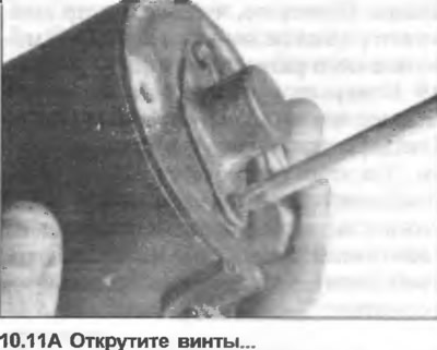
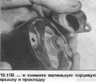
11. Unscrew the screws, remove the small end cap and gasket (photo).
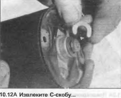
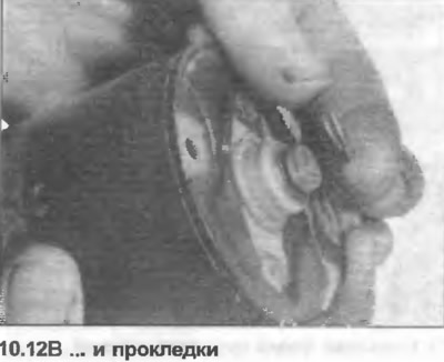
12. Remove the C-clamp, remove the shim, noting the exact number of shims, as they determine the axial play of the anchor (photo).
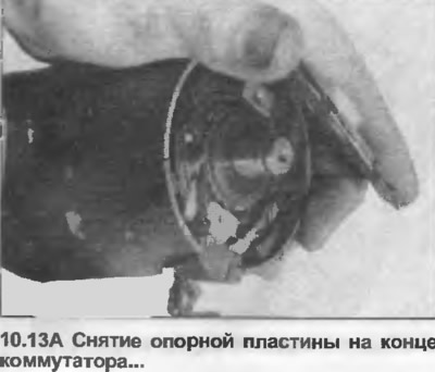
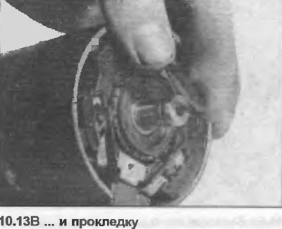
13. Remove the support plate at the end of the commutator, then the gasket (photo).
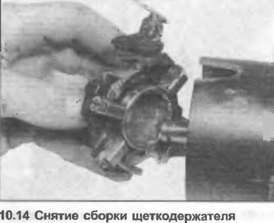
14. Before removing the brush holder assembly, prepare a socket with a diameter approximately equal to the commutator diameter. Position the socket against the commutator, then pull the bushings and the holder assembly onto the socket (photo).
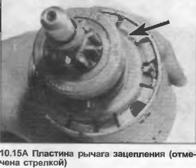
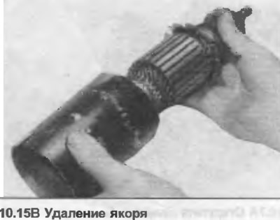
15. Mark the position of the engagement lever plate relative to the yoke, then remove the anchor (photo).
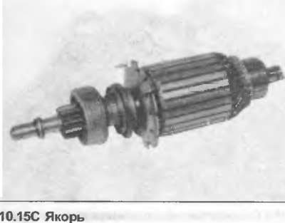
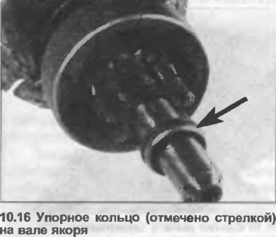
16. Use a metal pipe to move the thrust ring away from the retaining ring, then remove the retaining ring and remove the thrust ring (photo).
17. Pull the drive gear off the anchor.
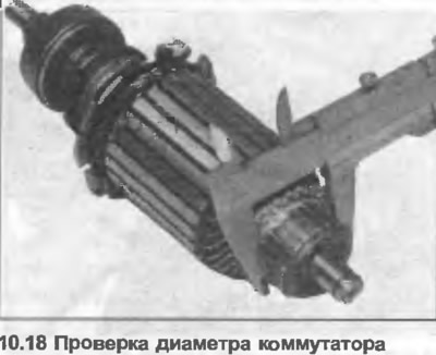
18. Clean all parts in kerosene, wipe dry, then check their condition. Check the condition of the drive gear teeth, make sure that the freewheel rotates in one direction only. If the shaft bushings are worn, they can be removed and new ones installed. However, new bushings must be immersed in hot oil for about five minutes. Clean the commutator with a rag soaked in a suitable solvent. Minor wear can be removed with fine sandpaper, but deep wear requires processing the commutator on a lathe. Check that the commutator diameter is not less than the specified minimum size (photo).
19. Measure the length of the brushes. If it is less than the minimum length given in the Specifications, install new brushes. This will require the use of a soldering iron, so be careful not to get solder on the braided wire, it may interfere with the free movement of the brushes in their holder.
20. Assembly is carried out in reverse order.