



Table of contents: Fasteners - general information ↓ Dimensions and strength classes of… ↓ Method and procedure for tightening… ↓ Disassembling the components ↓ Gasket surfaces ↓ Tips for removing hoses ↓ Tool ↓ A set of tools for routine… ↓ Special tool ↓ Purchasing a tool ↓ Care and storage of the instrument ↓ Workplace equipment ↓
There are several methods for performing vehicle maintenance and repair procedures, to which the reader will find references in the text of this Manual. Following the suggested instructions will make the amateur mechanic's work more efficient, will allow the best organization and high-quality execution of various technical procedures, and will be the key to the full performance of all necessary work.
Fasteners - general information
Fasteners are nuts, bolts, studs and screws used to connect two or more parts together. When working with fasteners, you should always remember some things. Almost any threaded fastener uses one or another type of locking and locking devices. These can be lock washers, lock nuts, lock flags or a special locking sealant for threaded connections. All used fasteners must be absolutely clean and straight, with undamaged threads and unrounded corners of hexagonal heads for the key. It is a rule to replace damaged fasteners without fail. Special self-locking nuts with nylon or fiber inserts cannot be reused, since they lose their locking properties when loosened and must always be replaced during assembly.
fasteners must be treated with a special penetrating compound before loosening to make them easier to unscrew and to avoid damage. Many mechanics prefer to use turpentine for this purpose, which is conveniently applied from a special small canister with a long spout. After wetting the fastener with the penetrating compound, let the product soak the oxidized contact layer thoroughly for several minutes. Heavily rusted fasteners can be cut off with a chisel, sawed off with a hacksaw, or removed with a special nut splitter.
When a bolt head is sheared off or a stud is broken off on an assembly, the remaining threaded portion can be drilled out or extracted with a special extractor. Most auto repair shops can undertake this and other (for example, restoration of stripped threads in threaded holes), repair procedures.
Flat and lock washers must always be installed in their original positions during assembly. Damaged washers must be replaced without fail. Between the lock washer and the soft metal surface (for example, aluminum), when fastening thin sheet metal or plastic parts, always use flat washers.
Dimensions and strength classes of fasteners
For many reasons, vehicle manufacturers are increasingly using metric fasteners. However, it is important to know the difference between the two (more versatile) fasteners and sometimes used SAE standard fasteners (or American). Despite the external similarity, the elements of these two types of fasteners are not interchangeable.
All bolts, both SAE and metric, are rated by diameter, thread pitch, and length. For example, an SAE 1/2 - 13 x 1 bolt is one-half inch in diameter, has 13 threads per inch, and is 1 inch long.
Dimensions/strength class markings for standard (SAE and USS) bolts
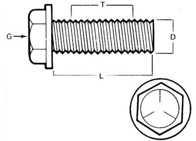
- G - strength class marking
- L - length (in inches)
- T - thread pitch (number of threads per inch)
- D - nominal diameter (in inches)
Metric bolt M12 - 1.75 x 25 has a diameter of 12 mm, thread pitch (distance between adjacent turns) 1.75 mm and 25 mm long.
Dimensions/Grade Markings for Metric Bolts
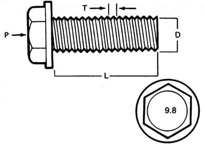
- P - strength class
- L - length (in mm)
- T - thread pitch (distance between adjacent turns in mm)
- D - nominal diameter (in mm)
Both bolts are almost identical in appearance, but are not interchangeable.
In addition to the above features, both metric and SAE bolts can be identified visually by inspecting the head. For starters, the distance between the flats of the head of a metric bolt is measured in millimeters, while the American bolt is measured in inches (the same is true for nuts). As a result, an SAE standard wrench is not suitable for use with metric fasteners, and vice versa. In addition, most SAE standard bolts usually have radial notches on their heads that determine the maximum allowable tightening torque (degree of strength) bolt. The greater the number of notches, the higher the permissible force (cars typically use bolts with strength classes from 0 to 5). The strength class of metric bolts is determined by a digital code. The code numbers are usually also cast on the bolt head (automobiles typically use bolts of strength classes 8.8, 9.8, and 10.9).
Marking of the strength class of bolts
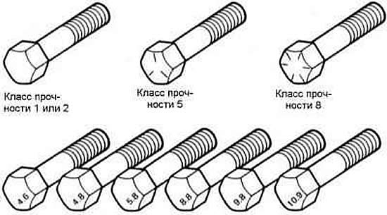
- top - standard /SAE/USS
- below - metric
Also, by the strength class marks, you can distinguish SAE nuts from metric ones. To identify the strength class of standard nuts, dot marks are used, stamped on one of the end surfaces, while the marking of metric nuts is made using, again, a digital code. The greater the number of dots/digital code value, the higher the permissible tightening force of the nut.
Strength class marking of standard hex nuts

- Hex nut
- Strength class 5
- Class Identification - Three Dots
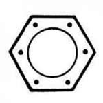
- Hex nut
- Strength class 8
- Class Identification - Six Dots
Metric Hex Nut Strength Class Markings

- Hex nut
- Strength class 9
- Class Identification - Arabic 9

- Hex nut
- Strength class 10
- Class Identification - Arabic 10
The ends of metric studs are also marked according to their strength class. Large studs are marked with a digital code, while smaller ones are marked with geometric shapes.
Marking the strength class of metric studs
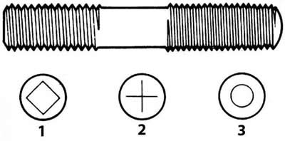
- 1 - Strength class 10.9
- 2 - Strength class 9.8
- 3 - Strength class 8.8
It should be noted that a significant portion of fasteners, especially those of strength class 0 to 2, are not marked at all. In this case, the only way to distinguish American fasteners from metric ones is to measure the thread pitch, or compare the threads with the threads of a uniquely identified element.
It should be remembered that only small fasteners fall under the SAE classification. Larger elements with non-metric threads are American Standard (USS) fasteners.
Since the fasteners are of the same geometric size (both standard and metric) may have different strength classes; when replacing bolts, nuts and studs, special attention should be paid to ensuring that the strength class of the newly installed elements matches the strength class of those removed.
Method and procedure for tightening threaded connections
Tightening of most threaded connections should be carried out with forces determined by the requirements of the Specifications given at the beginning of each Chapter of this Manual (the tightening force of a fastener should be understood as the torque applied to it). Overtightening can result in failure of the fastener, while undertightening can result in unreliable mating of the mating components. Bolts, screws and studs, depending on the material they are made of and the diameter of the threaded section, usually have strictly defined permissible tightening forces, many of which, as mentioned above, are listed in the Specifications at the beginning of each Chapter. Strictly adhere to the recommendations for tightening forces for the fasteners used on the vehicle. To tighten fasteners not listed in the Specifications, use the permissible torque chart below. The values in the table are oriented towards fasteners of strength classes 2 and 3 (higher grade fasteners allow for greater tightening force), in addition, it is implied that dry tightening is carried out (with ungreased threads) fasteners screwed into steel or cast (not aluminum) detail.
Metric threads
| M6 | 9-12 Nm |
| M8 | 19-28 Nm |
| M10 | 38-54 Nm |
| M12 | 68-96 Nm |
| M14 | 109-154 Nm |
Pipe threads
| 1/8 | 7-10 Nm |
| 1/4 | 17-24 Nm |
| 3/8 | 30-44 Nm |
| 1/2 | 34-47 Nm |
American standard threads
| 1/4 - 20 | 9-12 Nm |
| 5/16 - 18 | 17-24 Nm |
| 5/16 - 24 | 19-27 Nm |
| 3/8 - 16 | 30-43 Nm |
| 3/8 - 24 | 37-51 Nm |
| 7/16 - 24 | 55-74 Nm |
| 7/16 - 20 | 55-81 Nm |
| 1/2 - 13 | 75-108 Nm |
A fastener located around the perimeter of a component (such as cylinder head bolts, oil pan bolts and various covers) must be loosened and tightened in a strictly defined order to avoid deformation of the part. The order of tightening and loosening such fasteners is given in the text of the relevant Chapters of the Manual, as well as in the illustrations. If a special order is not specified, then in order to avoid deformation of the component, the following instructions should be followed.
At the first stage, all bolts/nuts should be tightened by hand. Then, each of the fasteners is tightened one more full turn in turn, and the transition from one bolt/nut to another should be carried out in a diagonal order (criss-cross). Next, returning to the first element, repeat the procedure in the same order, tightening the fasteners another half turn. Continue the procedure, tightening each element now by a quarter turn at a time until they are all tightened to the required force. When loosening the fasteners, you should act in a similar manner, but in reverse order.
Disassembling the components
Disassembly of all components must be carried out in such a manner that during assembly each part could be installed in its original place and in the correct way. Try to remember the characteristic external features of the unit in the assembly, if necessary, make a landing marking of parts, the installation of which in place can be performed in an ambiguous way (for example, a grooved thrust washer on a shaft, etc.). It is a good idea to lay out the removed parts on a clean work surface in the order in which they were removed. It may also be helpful to make simple schematic sketches or take step-by-step photographs of the component being disassembled.
When releasing fasteners, try to mark their original position on the assembly. Often, installing fasteners and washers in their original place immediately after removing the corresponding part helps to avoid confusion during assembly. If this is not possible, all fasteners should be placed in a specially prepared box divided into sections and appropriately marked, or simply in separate marked boxes. This approach is especially useful when working with components consisting of many small parts, such as a carburetor, generator, valve mechanism, instrument panel or decorative trim elements.
When disconnecting electrical contacts and connectors, pay attention to marking the wires or harnesses using tape with a digital or letter code applied to it.
Gasket surfaces
On all vehicles, sealing gaskets are used to seal the junction of the mating surfaces of two or more parts and serve to prevent leaks of oils and other working fluids and maintain increased pressure/vacuum inside the assembly.
Often such gaskets are coated with a liquid or paste-like sealing compound before installation (sealant). Sometimes, over time or under the influence of elevated temperatures or pressure, the mating surfaces become so strongly pressed together that separating the parts becomes difficult. In many cases, successful separation of the components is assisted by tapping them from the outside along the perimeter of the joint with a soft-faced hammer. You can also use a regular hammer for this purpose, striking through a wooden or plastic spacer. Do not tap cast housings or components that are sensitive to shock. When this type of difficulty arises, always first check whether all fasteners have been removed.
Avoid levering the parts with a screwdriver or pry bar inserted into the joint area, as this can easily damage the mating surfaces, which will subsequently lead to the development of leaks. If it is impossible to avoid levering the assembly elements, use the handle of an old broom for this purpose, but remember that all the resulting splinters must be carefully removed from both the mating surfaces and from the internal cavities of the components of the unit being dismantled.
After separating the parts, their mating surfaces should be carefully cleaned using a scraper to remove traces of the old gasket material. Hardened fragments can be pre-softened using a rust converter or a special chemical composition. In this case, a piece of copper tube with a flattened and sharpened end can be used as a scraper. The remains of some gaskets can easily be removed using a copper brush, however, regardless of the method used, the mating surfaces must be completely clean and dry as a result of the treatment. If for any reason the mating surface is damaged, fill the defects with gasket sealant before assembling the unit. In most cases, non-hardening gasket sealant should be used (or not completely hardening) sealant.
Tips for removing hoses
If your vehicle is equipped with an air conditioning system, do not disconnect any hoses from the system components under any circumstances until the system has been discharged by an air conditioning specialist at a service station.
The precautions to be taken when removing hoses are very similar to those taken when removing gaskets. Avoid damaging the surfaces of the fittings and pipes onto which the ends of the hoses are pulled, as this may cause leaks to develop.
The latter requirement applies especially to the procedure for removing radiator hoses. Due to various chemical reactions occurring in the cooling system, rubber hoses often adhere to the surfaces of fittings and pipes. To remove a hose, first loosen the clamp that secures it. Then use pliers to grab the hose near the clamp and begin to rotate it on the fitting/connecting pipe to the right and left. Continue acting in this manner until the hose is completely free, then remove the hose from the fitting.
A small amount of silicone or other lubricant injected into the gap between the nipple and the hose will save effort. Before installing the hose, lubricate the inner surface adjacent to the end, as well as the outer surface of the nipple with a solution of soapy water or a small amount of silicone lubricant.
As a last resort, or in case of a clear need to replace the hose with a new one, the end of the hose put on the nipple can be cut with a knife and then separated from the surface of the nipple. In doing so, try not to damage the metal of the nipple/connecting pipe with the blade.
If the hose clamp is damaged, replace it with a new one. Twist-type clamps usually loosen over time, so regardless of their condition, it is better to replace them with more practical screw or worm-type clamps.
Tool
Selecting a quality tool is one of the fundamental requirements for anyone planning to perform maintenance or repair procedures on their vehicle themselves. At first glance, the costs associated with purchasing the required set of tools may seem disproportionately large, but when compared with the costs associated with performing routine maintenance and simple repairs to a vehicle at a service station, they appear quite reasonable.
In order to systematize the approach to choosing the tools needed for car repair and maintenance, three lists of tools are provided below, conventionally titled as:, and. Car owners who do not have practical experience in mechanical work should start with performing procedures limited to the use of tools from the first list, while improving their skills and gradually expanding the range of their activities. As you acquire skills, you can move on to performing more complex tasks, gradually expanding the range of tools at hand. After some time, the acquired experience will allow you to move on to performing more complex work requiring the use of a tool from the second list (for general and major repairs of the car). When the performer's qualifications reach a sufficiently high level and allow significant savings on independent performance of complex repair procedures, you can think about purchasing a special tool.
A set of tools for routine maintenance and minimal repairs of a car
The list below includes the minimum number of tools needed to perform routine maintenance and minor repairs on your vehicle. The authors of this guide recommend starting with a set of combination wrenches (with a regular open-end head on one end and a socket head on the other). Despite the increased cost of this set compared to the cost of a set of conventional open-end wrenches, the costs will be justified, since such wrenches have the advantages of both types.
- Set of combination wrenches from 8 to 19 mm
- Adjustable wrench (up to 35 mm)
- Spark plug wrench with rubber insert (petrol models)
- Spark plug gap adjustment tool (petrol models)
- Set of measuring probes
- Brake Bleeding Nipple Key
- Screwdrivers:
- With a flat tip (100mm long and 6mm in diameter)
- With a cross sting (100mm long and 6mm in diameter)
- Combination pliers
- Hacksaw for metal with a set of blades
- Tire inflation pump
- Tire pressure gauge
- Grease gun (syringe)
- Oil canister
- Fine grit sandpaper
- Wire brush
- Tool for stripping terminals and contacts of battery wires
- Oil filter removal key
- Funnel (medium size)
- Supports for fixing the car in a raised position (2)
- Drainage tank
Warning:If routine maintenance procedures include performing basic adjustments, you will also need to purchase a high-quality strobe light and a combined tachometer / instrument to measure the duration of the closed state of the breaker contacts. Despite the fact that these tools are included in the list of special tools, they are mentioned here in view of the absolute necessity of their use for high-quality tuning of the engine ignition, which is part of the car's routine maintenance procedures.
A set of tools for general and major car repairs
This tool is absolutely necessary for any car engine repair operations and is offered in addition to the first list. This list includes a complete set of replaceable socket heads. Despite the considerable cost, a set of replaceable heads brings invaluable benefits due to its versatility and ease of use, especially in combination with the included drives of various types. It is recommended to give preference to drives with a cross-section of 1/2 inch (and not 3/8 inch), because they, although more expensive, can be used with almost any type of torque wrench (ideally, a good mechanic should have both types of drives at his disposal). A cheaper alternative to a set of socket heads is a set of tubular wrenches.
- Set of replacement socket heads (including type heads) (or tubular wrenches), sizes corresponding to the sizes of wrenches from the previous list
- Ratchet reversible drive (for use with interchangeable socket heads)
- Gate length 250 mm
- Cardan drive (for use with interchangeable socket heads)
- Torque wrench (with the same size drive as for socket heads)
- Self-locking pliers
- Round-head hammer (about 230 g)
- Soft-faced hammer (plastic or rubber)
- Screwdrivers:
- With a flat tip (150 mm long and about 6.5 mm in diameter)
- With flat tip (strong No.2, 8 mm)
- With cross blade (No. 3 x 8 inches (203 mm))
- With a cross blade (strong No.2)
- Clamping pliers
- Pliers:
- For electricians (with insulated handles)
- Narrow-nosed (needle nose pliers)
- For retaining rings (internal and external)
- Chisel 25 mm
- Scraper (made from a copper tube flattened and pointed at one end)
- Scriber (scribe)
- Kerner
- Beards with a thin sting (1.6, 3.2, 4.8 mm)
- Hose clamp kit
- Brake Bleeding Kit
- Set of drills
- Steel ruler/flatness gauge
- Set of Allen key rods (Allen) (for hexagon socket heads)
- Set of files
- Wire brush (large)
- Second set of supports
- Jack (hydraulic or scissor type)
- Carrying case with closed lampshade
Warning: Another tool that is always needed is an electric drill with a chuck for up to 9.5 mm with a set of good quality drill bits.
Special tool
This category includes tools that are quite expensive, not needed regularly, or require following the manufacturer's instructions when using. If the hobby mechanic does not frequently perform complex mechanical operations, purchasing such a tool will be a bad investment - it would be wiser to buy it together with friends, or rent it from auto repair shops as needed.
The list includes only those tools that can be found in retail or that are produced for distribution to service centers of representative departments of car manufacturers. Sometimes in the text of the Manual the reader will encounter references to such special tools. Usually the authors try to simultaneously offer an alternative method that allows to avoid the obligatory use of a hard-to-find tool. In case it is impossible to avoid using a special tool, and its acquisition for use is problematic, it is better to entrust the performance of the corresponding work to car service specialists.
- Valve Spring Compressor Tool
- Valve grinding tool
- Piston Ring Groove Cleaning Tool
- Piston Ring Crimping Tool
- Piston Ring Installation Tool
- Cylinder Compression Gauge (compression meter)
- Countersink for processing cylinder edges
- Hone for processing cylinder mirrors
- Cylinder Bore Gauge
- Micrometer (micrometers) and/or dial caliper
- Clutch Disc Centering Tool
- Ball joint extractor
- Universal type puller
- Impact screwdriver
- Dial Gauge Set
- Stroboscope (with inductive sensor)
- Hand Combination Pump (vacuum/pressure)
- Set of taps and dies
- Tachometer/breaker contact duration measuring instrument
- Universal tester for electrical measurements
- Lifting rigging
- Tool for removing/installing brake springs
- Trolley (trolley) jack
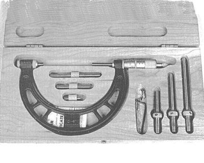
Micrometer with a set of attachments.
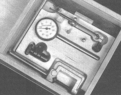
Dial gauge with a set of clamps and attachments.
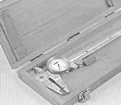
Dial/vernier caliper.
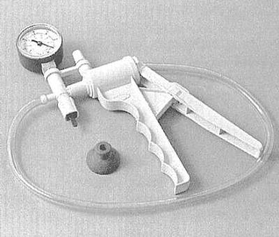
Hand operated vacuum pump.
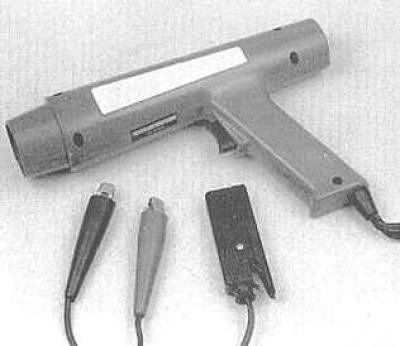
Stroboscope.
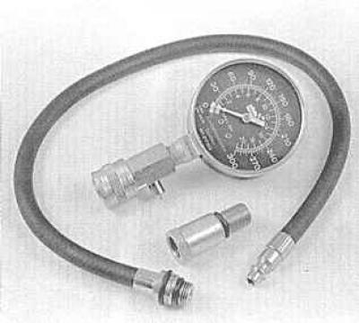
Compression gauge with a nozzle for installation in spark plug holes.
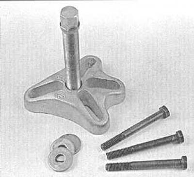
Damper/steering wheel remover.
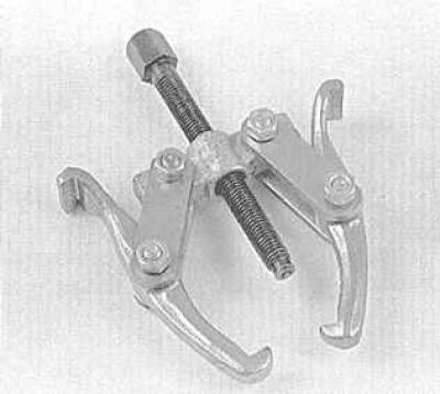
General purpose puller.
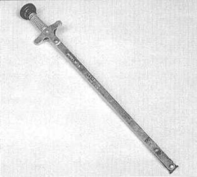
Tool for removing hydraulic tappets.
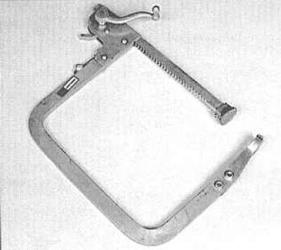
Valve spring compressor tool.
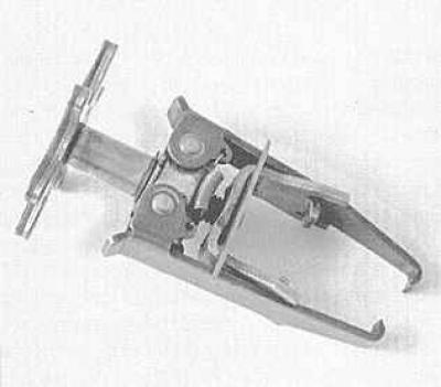
Valve spring compressor tool.
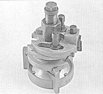
Countersink for removing stepped wear in a cylinder.
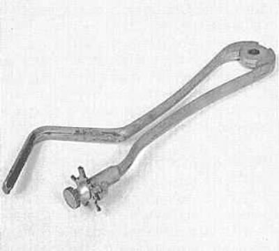
Device for cleaning piston ring grooves.
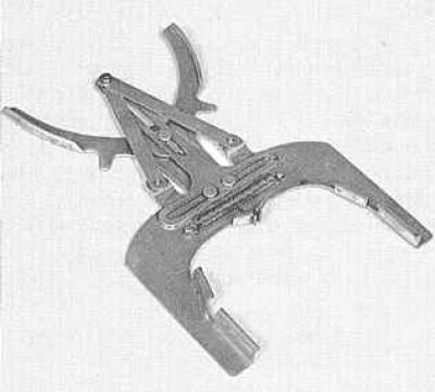
Tool for removing/installing piston rings.
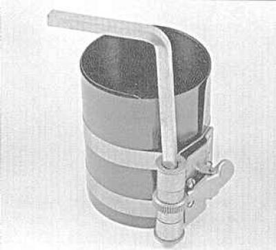
Piston ring crimping tool.
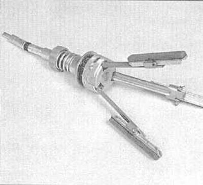
Hone for processing cylinder mirrors.
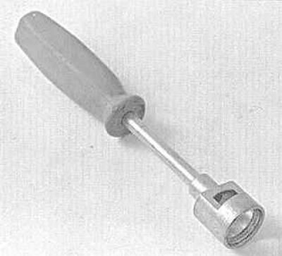
Tool for removing brake shoe guide spring cups.
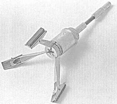
Hone for processing brake cylinders.
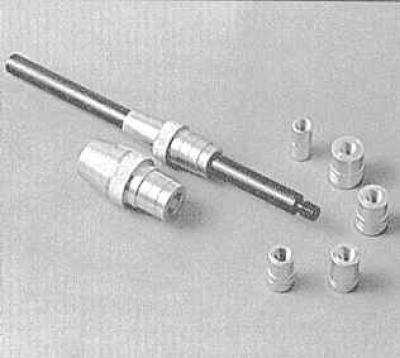
Clutch disc centering tool.
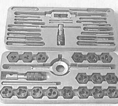
A set of taps and dies.
Purchasing a tool
A novice mechanic can be offered several practical tips in terms of purchasing the tools necessary to perform car maintenance and repair procedures. When preparing to perform routine maintenance or minimal car repairs, it is reasonable to purchase tools individually. On the other hand, if you are planning larger-scale work, it is easier and more reliable to buy a set of modern tools in a retail store. Purchasing a set is usually somewhat cheaper than individual purchases and is often accompanied by a tool box. In the future, to expand the range, individual tools, additional sets and a larger tool box can be purchased. Gradually expanding the set of tools will allow you to stretch out the costs and decide on the choice of really necessary tools.
Specialized tool stores are the only source for some specialized tools. Regardless of the source, avoid cheap purchases, especially when choosing screwdrivers and socket heads, as their service life will likely be short. The costs associated with replacing and restoring a cheap tool will ultimately be incomparably greater than the costs of a one-time purchase of a quality product.
Care and storage of the instrument
A good tool is a valuable investment, so it is wise to take care to keep it clean and always ready for use. After using the tool, before storing it, always wipe its surface thoroughly with a clean, dry cloth, removing traces of dirt, grease and metal particles. Never leave the tool scattered around. After completing work, carefully check the space under the hood and under the car for forgotten tools.
A tool rack mounted in a convenient location on the garage wall is ideal for storing tools such as screwdrivers, pliers, hammers, etc. Sets of wrenches and socket heads should be stored in metal boxes. Precision measuring tools should be stored in places that are free from corrosion, dry, and clean.
You should always pay attention to the condition of the working surface of the tool. The striking part of the hammer head is subject to riveting during use, and screwdrivers lose the sharpness of their tips over time. Do not skimp on spending a little time and attention to remove riveting with sandpaper or a file and tidy up the cutting edges. Replace irreversibly worn or damaged tools in a timely manner.
With careful care, the instrument can serve faithfully for a very long time.
Workplace equipment
When talking about tools, we cannot help but mention the equipment of the workplace. If more serious work is to be carried out than simple maintenance of the vehicle, it is necessary to take care of the preparation of a suitable work site.
It must be admitted that many car enthusiasts are forced to dismantle the engine and other similar work far from a garage or workshop. However, in any case, an important requirement is the presence of a roof or awning.
If possible, any procedures for disassembling parts of vehicle systems should be performed on a clean workbench with a flat work surface, or a sturdy table of a comfortable height. The workbench must be equipped with a vice with a jaw opening of up to 100 mm and with soft pads on the jaws.
As mentioned above, the work site should be equipped with a clean, dry place for storing tools, lubricants and cleaning fluids, putties, paints and varnishes, etc.
It should be noted that an absolutely necessary tool is an electric drill, therefore, the work site must be equipped with a power source for its connection. Having a drill with a chuck up to 9.5 mm and a set of high-quality drills will greatly facilitate the implementation of many procedures.
Finally, the work area should always have an adequate supply of old newspapers and clean, lint-free rags available for picking up spills and wiping down the work area, tools, and vehicle parts.
Used working fluids should be handed over to recycling centers in sealed containers.
Never carry out any work on the uncovered painted surface of the car body panels, use protective pads on the fenders, or, at worst, cover the polished surfaces with old blankets.