
Table of contents: Problems with gear shifting ↓ Adjusting the gear shift mechanism ↓ Execution order ↓
The engine power is transmitted via the clutch to the input shaft of the gearbox. On this input or drive shaft are 6 gears (including reverse gear), which are permanently connected to six corresponding gears on the so-called output shaft. These gears can rotate freely until a certain gear is engaged and one of the gears engages with the corresponding opposite gear on the drive shaft. The ratio of the number of teeth of each pair of gears gives the corresponding gear stage. In our Audi – as in all passenger cars – there are fully synchronized forward gears. In addition, the reverse gear is also synchronized in order to avoid grinding when this gear is engaged.
The gears on the drive and output shafts rest on "needles" (pin rollers). Thus, there is no rigid connection between the shafts and the gears. The gears, as already mentioned, always remain engaged.
When changing gear, a connection is created between the pinion and the shaft, not between the pinions. To synchronize the speed of rotation of the shaft and the pinion, one part of the shaft slides relative to one part of the other shaft by means of friction elements.
Due to friction, the shaft, rotating faster, is slowed down until the synchronous rotation can create a connection that ensures the transmission of the power flow. Since it takes fractions of a second to synchronize the speed, you should not "tear" the gearshift lever with force, especially when the engine is cold and the oil in the gearbox is still thick.
Problems with gear shifting
If gears are difficult to shift or if the gear shift becomes difficult to shift after a long period of parking, then most often the source of the fault is in the clutch and not in the gearbox (see section Troubleshooting help in the Clutch chapter). The gear shift adjustment described below serves to bring the gear shift lever into the correct position and thereby correct the shift strokes.
Adjusting the gear shift mechanism
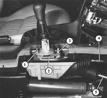
This model of the car clearly shows the gear shift mechanism in section:
- 1 and 3 - fastening nuts of the ball gear shift mechanism housing (2);
- 4 - rigid trigger rod;
- 5 - gear shift rod.
Execution order
1. Unscrew the gear shift knob.
2. Remove the gear shift lever cuffs by removing the lower cuff frame from the clamps.
3. Place the gear shift lever in neutral position.
4. Installation in longitudinal direction: check the distance "a" = 37 mm, if necessary, adjust it as follows:
5. Slightly loosen bolt "2" (picture below) and move the gear shift plate so that the distance is correct.
6. Tighten "2" to a tightening torque of 25 Nm.
7. Lateral adjustment: loosen nuts "3" and "4".
8. Tighten nut "3" to 25 Nm, nut "4" to 10 Nm.
9. Loosen bolt "1".
10. Place the gear shift lever vertically, tilted slightly backwards, and position it so that both projections of the ball stop are the same distance from the ball housing.
11. Tighten bolt "1" to 25 Nm.
12. Finally, check the operation: the gear shift lever in neutral position should be in the 3/4th gear plane.
13. Check all gears by shifting, paying attention to the operation of the reverse lock.
14. Fine adjustment: If the adjustment is still not satisfactory, loosen nuts "3" and "4" of the ball gear housing.
15. Move the lever to the right until it stops (gear) and at the same time press the ball housing to the left towards the gear shift lever.
16. While holding the named parts in this position, tighten nuts "3" and "4" again.
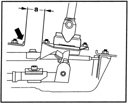
Adjustment of the gear shift lever in the longitudinal direction: dimension "a" is 37 mm.
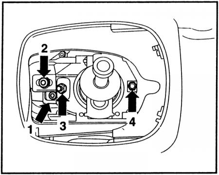
Adjusting the gear shift mechanism: In this figure, the bolts and nuts mentioned in the text are indicated by numbers.
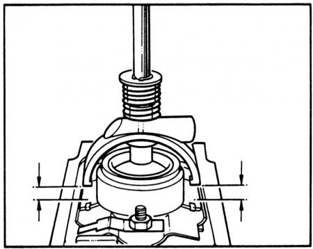
Adjusting the gearshift lever in the transverse position: both projections of the ball stop must be at the same distance "a" from the ball housing.
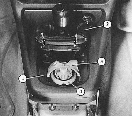
To access the gearshift lever adjusting screw, lift the cuff (2). To do this, remove the cuffs from the mounting slots (arrows) of the lower frame. Then remove the sound insulation (1). The following are visible:
- 3 - ball stop;
- 4 - ball housing.