



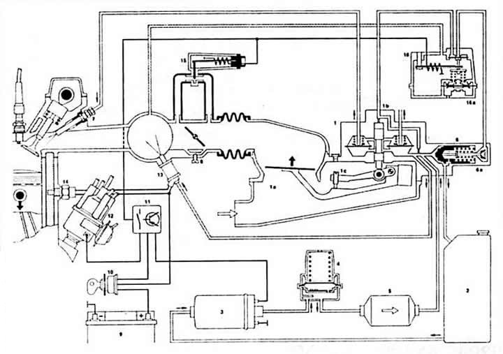
K-Jetronic diagram
1 - mixture regulator
1a - air quantity meter
1b - fuel dispenser
1c - CO adjustment screw
2 - gas tank
3 - Electric fuel pump
4 - fuel pressure accumulator
5 - fuel filter
6 - pressure regulator in the system
ba - valve
7 - injection valve
8 - idle speed adjusting screw
9 - battery
10 - ignition switch
11 - fuel pump relay
12 - ignition distributor
13 - cold start valve
14 - temperature and time sensor switch
15 - additional air valve
16 - heating regulator
16a - full load membrane
K-Jetronic is a mechanical injection system that continuously injects fuel into the intake manifold before the injection valve. The mechanical basis corresponds in many ways to KE-Jetronic. Some operating recommendations are given in the chapter KE-Jetronic.
The pressure accumulator keeps the fuel under pressure, also for a long time after the engine is turned off. Thanks to this, the formation of vapor locks is prevented and the hot start mode is improved.
The fuel pump relay supplies the fuel pump, auxiliary air valve and preheat regulator with current. The relay overflows the current to the pump when the ignition is switched off and if no more ignition pulses are generated (Engine stopped, ignition off). In addition, the relay interrupts the fuel supply when the highest speed of 6500-6700 rpm is reached, until the speed decreases.
The cold start valve injects additional fuel into the intake manifold when the engine is cold during startup to help the engine start more easily.
The temperature-time sensor-switch regulates the injection time of the cold start valve.
The system pressure regulator maintains a pressure of 5.2-5.9 bar.
The thermoelectric valve of additional air stabilizes the number of revolutions during engine warm-up.
The warm-up regulator enriches the mixture during warm-up.
Caution: When working on the mechanical injection system, it is necessary to maintain impeccable cleanliness. Before removing the relevant parts, clean them with gasoline. The system is under pressure. Therefore, before replacing parts, slowly loosen the cold start valve to reduce the pressure. In doing so, wrap the fuel system pipe with a rag, as fuel may squirt out. Collect the protruding fuel with a rag.