
1. Remove the timing belt and crankshaft sprocket as described in Chapter 40.
2. Remove the tray as described in Chapter 42.
3. Remove the oil dipstick.
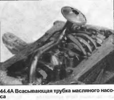
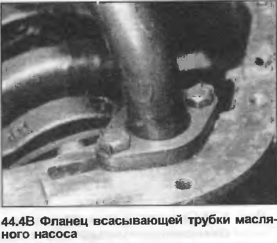
4. Unscrew the two bolts securing the oil suction pipe to the crankcase (photo). Knock back the keys of the locking plate on the suction pipe flange (photo), remove the bolts and the suction pipe.
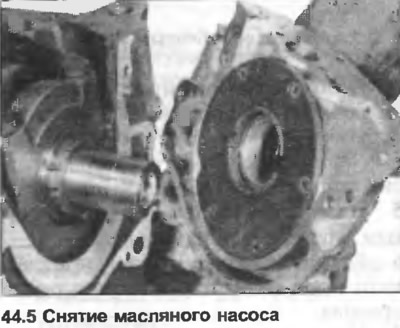
5. Unscrew the bolts securing the oil pump, remove the oil pump and gasket (photo).
6. Unscrew the screws securing the pump shield and lift the shield (photo).
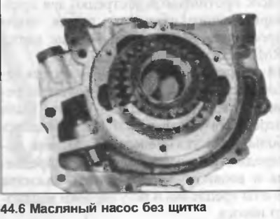
7. Check that there are marks on the visible surface of the gears. If not, make a mark to avoid confusion as to which side of the gears faced the engine before removal.
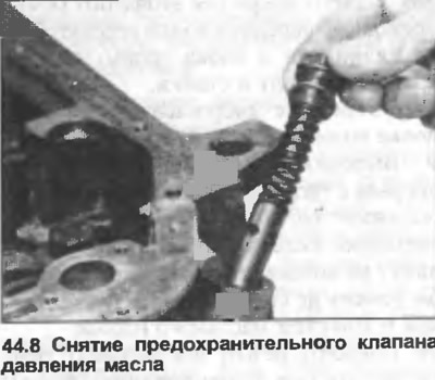
8. Unscrew the pressure relief valve, remove the plug, O-ring, spring and plunger (photo).
9. Clean all parts, check the condition of the pump body and shield, the plunger of the pressure relief valve and the bearing surface, check that the spring is not damaged or distorted. Check the condition of the gears. New gears can be used, but they must be installed in pairs.
10. Remove the seal from the front of the pump. Lubricate the lip of the new seal, insert the seal with the closed surface facing outward, and hammer it into place with a block. If there is a groove on the crankshaft in the area where the seal lip rubs, the seal can be pushed to the base of the groove so that the lip moves to the undamaged part of the crankshaft.
11. Assemble the pump by installing the gears and shield. The inner gear is positioned with the splined end facing the crankshaft, although the outer gear can be installed either way, it is recommended to install it as it was before removal. Some gears have a triangle, this mark should be facing forward.
12. Install the oil pump together with a new gasket, make sure that the protrusion on the crankshaft enters the groove on the internal gear.
13. Insert and tighten the bolts in a diagonal sequence to the specified tightening torque Specification.
14. Install the oil suction pipe together with the new gasket, tighten the bolts, bend the lock plate keys onto the flange bolts.
15. Install the dipstick, sump (Chapter 42), toothed drive belt and crankshaft sprocket (Chapter 40).