
Table of contents: Removal ↓ Installation ↓
The range of work that a car owner can perform on an automatic transmission independently is limited. However, targeted checks can help in identifying faults, which is very important for used cars. In case of any failure of the transmission, the fluid level in the transmission should be checked first. If a burning smell is felt when removing the dipstick, then a very complex defect of the automatic transmission disc brake is evident.
Removal
1. Place the vehicle on jack stands to ensure free access to the engine compartment and unimpeded work under the vehicle. The gearbox is removed downwards.
2. Disconnect the negative (-) cable terminal from the battery and remove the fairing.
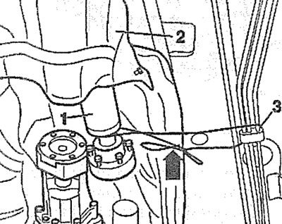
3. Remove the protective cover from the engine and disconnect the air intake 1 from the upper front cross member (see illustration).
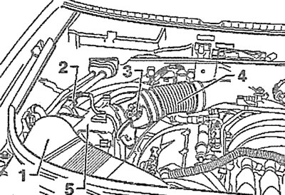
2.3. Disconnect the air intake 1 from the upper front cross member
4. Remove the supply air duct 4 by disconnecting plug 2 of the canister purge valve, releasing the valve from the holder and disconnecting plug 3 of the mass air flow sensor (see illustration 2.3).
5. Remove the air filter cover 6 (see illustration 2.3).
6. Unscrew the mounting bolts of the expansion tank of the cooling system and move it to the side without disconnecting the hoses, see the corresponding chapter.
7. Disconnect the lambda probe connectors on the exhaust manifolds of the right and left heads and release their wires from the holders.
8. Unscrew the upper nuts securing the inlet pipes to the exhaust manifolds, see the corresponding chapter.
9. Unscrew the upper bolts that connect the gearbox to the engine and that are accessible at this point.
10. Secure the engine with a hoist by the eyes. In workshops, a special beam is used for this purpose, installed above the engine compartment.
11. Remove the front wheels and engine guard if they have not been removed previously.
12. Remove the protective shields over the right and left drive shafts (see arrows in the illustration).
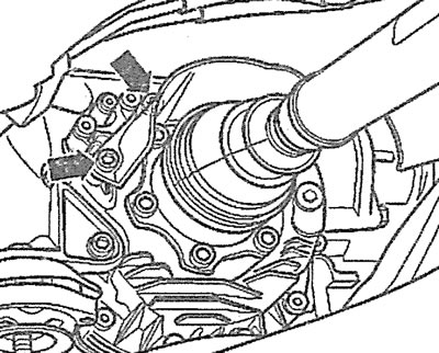
2.12. Remove the protective shields over the right and left drive shafts (see arrows)
13. Disconnect the right and left drive shafts from the flanges on the gearbox by unscrewing the mounting bolts. Secure the disconnected drive shafts to the body with wire so that they do not sag.
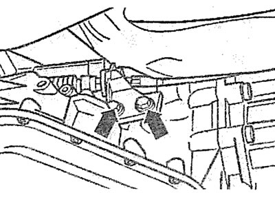
14. Unscrew the bolt securing the tachometer sensor on the left side of the gearbox and move the sensor to the side, and also disconnect the speedometer sensor plug (see arrows B and A in the illustration).
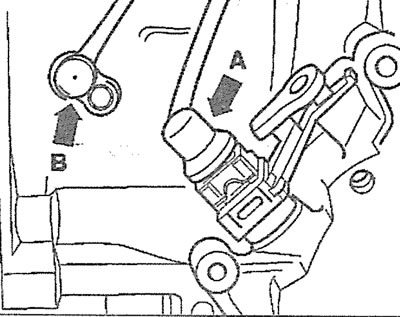
2.14. Unscrew the tachometer sensor mounting bolt and move the sensor to the side, and also disconnect the speedometer sensor plug (see arrows B and A)
15. Disconnect plug 1 of the selector, press stopper 2 and disconnect the plug on the transmission wiring harness (see illustration).
2.15. Disconnect plug 1 of the selector, press stopper 2 and disconnect the plug on the gearbox wiring harness
16. Unscrew the mounting bolts and remove the starter, see the corresponding chapter. Removing the starter is necessary to access the torque converter mounting bolts.
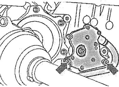
17. Unscrew the three bolts that secure the torque converter through the hole in the starter mounting seat. In order to bring out the next bolt that secures the torque converter into the hole, the engine should be turned by 1/3 of a turn (see illustration).
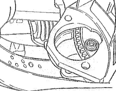
2.17. Unscrew the three bolts that secure the torque converter through the hole in the starter mounting seat
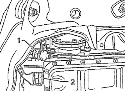
18. Disconnect the generator ventilation hose 1 and unscrew the transmission fluid circulation pipe holder bolt 2 (see illustration).
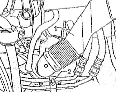
2.18. Disconnect the generator ventilation hose 1 and unscrew the transmission fluid circulation pipe holder bolt 3
19. Place a container under the transmission fluid circulation lines and disconnect lines 1 from the transmission fluid cooling radiator (see illustration). Seal the pipe openings with suitable plugs.
2.19. Disconnect pipes 1 from the transmission fluid cooling radiator: 2 - starter mounting bolt
20. Unscrew bolt 3 of the transmission fluid circulation pipe holder (see illustration 2.19).
21. Remove the rear section of the exhaust system if necessary, see the relevant chapter.
22. Unscrew the mounting bolts (see arrows in the illustration) and remove the protective shield B of the propeller shaft, connected to the Torsen differential cover.
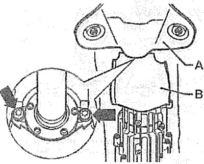
2.22. Unscrew the mounting bolts (see arrows) and remove the protective shield B of the propeller shaft
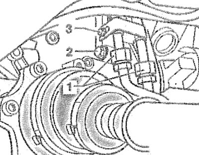
23. Unscrew the bolts securing the propeller shaft 1 to the gearbox, lower it onto the shield 2 and additionally secure it with wire to the holder 3 of the fuel lines (see illustration).
2.23. Unscrew the bolts securing the propeller shaft 1 to the gearbox, lower it onto the shield 2 and additionally secure it with wire to the holder 3 of the fuel lines
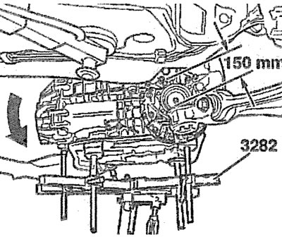
24. Install a suitable support under the gearbox. In workshops, a special support VAG 1383A with a plate 3282/19 is used for this purpose, which ensures proper fastening of the gearbox and allows it to be maintained in a horizontal position (see illustration).
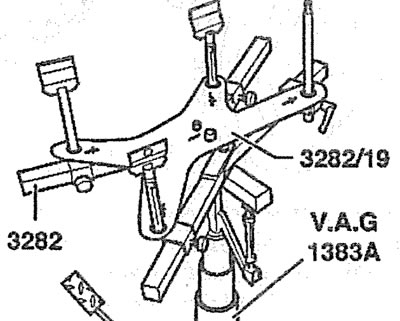
2.24. VAG 1383A support for removing the gearbox
25. Unscrew the mounting bolts and remove the right and left gearbox suspension supports.
26. Unscrew the selector mounting bolts (see arrows in the illustration) and move it to the side together with the wire. This operation is recommended to avoid damaging the selector.
2.26. Unscrew the selector mounting bolts (see arrows) and move it to the side along with the wire
27. Mark the mounting position of the gear shift rod support and remove the support by unscrewing the mounting bolts (see illustration).
2.27. Mark the mounting position of the gear shift rod support and remove the support by unscrewing the mounting bolts
28. Disconnect the gear shift cable end from the selector using the 80-200 wrench (see illustration).
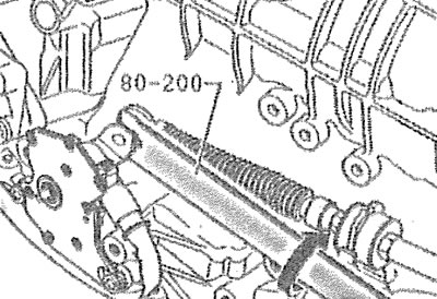
2.28. Disconnect the gear shift cable end from the selector using the 80-200 wrench
29. Vehicles with 6-cylinder TDI engine: Loosen bolt A behind the turbocharger by a few turns and turn spacer B in the direction of the arrow (see illustration). In this position, tighten the bolt A.
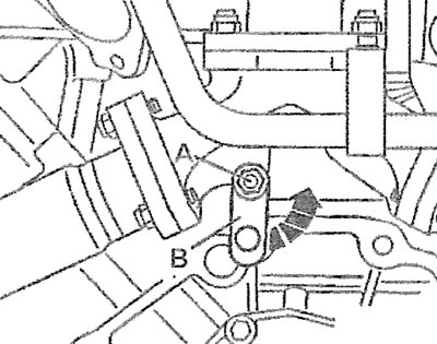
2.29. Loosen bolt A located behind the turbocharger by a few turns and turn spacer B in the direction of the arrow
Attention! To remove the gearbox, you need to lower the subframe by unscrewing the corresponding bolts that secure it.
30. Unscrew bolts 1 and 2 of the rear subframe support brackets on both sides, as well as the front bolts 3 (see illustration).
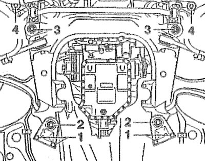
2.30. Unscrew bolts 1 and 2 of the support brackets for fastening the rear part of the subframe on both sides, as well as the front bolts 3
Attention! The vehicle manufacturer recommends that before performing this operation, you make sure, using a special device, that the holes for bolts 1 and 2 are in line with each other. If this is not the case, then after installing the gearbox/subframe, you should check the wheel alignment (see illustration 2.30a).
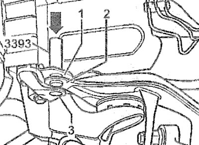
2.30a. Checking the alignment of holes for bolts 1 and 2 using the AUDI-3393 device
After unscrewing the bolts, the rear of the subframe drops approximately 150 mm.
31. Unscrew the lower bolts securing the intake pipes and disconnect them if this has not been done earlier.
32. Remove the remaining transmission-to-engine mounting bolts and lift the transmission away from the engine. If necessary, use a pry bar to disengage the torque converter from the drive plate (see illustration). The torque converter must remain in the gearbox. Make sure it does not fall out.
2.32. Unscrew the remaining bolts securing the gearbox to the engine and push the gearbox away from the engine
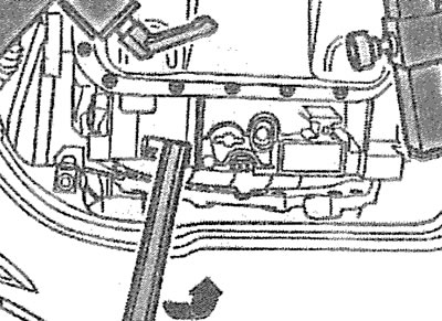
33. Tilt the gearbox, lowering its rear part by adjusting the support stop (see arrow in illustration).
2.33. Tilt the gearbox, lowering its rear end by adjusting the support stop (see arrow)
34. Make sure all wires and pipes are disconnected and nothing will interfere with the transmission lowering on the support.
35. Lower the box on the support down and remove it from under the car.
Installation
The gearbox is installed in the reverse order of its removal.
Make sure the torque converter is properly positioned in the box and does not fall out during installation.
36. Be sure to use the original bolts to attach the torque converter to the clutch drive plate. Otherwise, the torque converter will be damaged.
37. Screw in and tighten the gearbox-to-engine mounting bolts (see illustration).
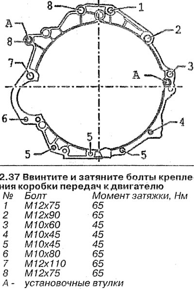
2.37. Screw in and tighten the gearbox mounting bolts to the engine
38. Top up the transmission fluid level if necessary.
[The article is a reprint of material from AUDIMANUAL]