
Table of contents: Removal ↓ Installation ↓
Removal
Attention! The shock absorber strut is removed together with the support bracket of the upper arms. Before removing the strut, it is necessary to remove air from the air spring. The manufacturer recommends performing this operation using a diagnostic tester.
1. Mark the position of the front wheel to be removed on the hub with paint. This will allow you to install the balanced wheel in its original position during assembly.
2. Remove the cap or protective cover and loosen the bolts securing the wheel to be removed without jacking up the vehicle.
3. Remove air from the air spring.
4. Jack up the front of the car, place it on jack stands and, after unscrewing the mounting bolts, remove the wheel.
5. Support the subframe with a garage jack, placing a wooden block underneath so that the suspension does not sag after disconnecting the shock absorber strut. Otherwise, damage to the lower suspension arm supports may occur.
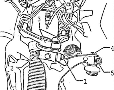
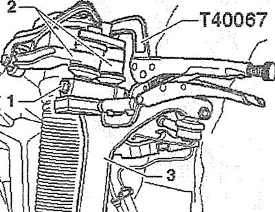
6. Unscrew the union nut 1 of the air supply line on the valve 2 for maintaining the residual pressure and release the line from the holder on the shock absorber strut (see illustration). Seal the openings on the valve and pipeline with suitable plugs to prevent contamination from entering them.
2.6. Unscrew the union nut 1 of the air supply line on the valve 2 for maintaining residual pressure
Attention! Dismantling of valve 2 for maintaining residual pressure is not permitted.
7. Remove clamp 3 with pliers or tongs (see illustration 2.6). It is not necessary to install this clamp subsequently.
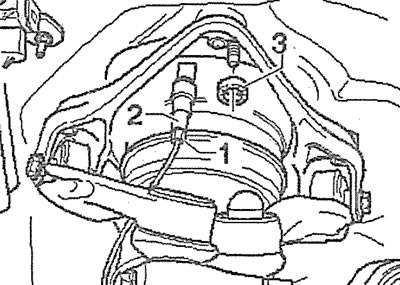
8. Unscrew nut 1, remove bolt 2 with a hexagonal head, which locks the pins of the ball joints of the upper arms on the steering knuckle, and disconnect both arms from the steering knuckle by pushing them upwards (see illustration).
2.8. Unscrew nut 1, remove bolt 2 with a hexagonal head and disconnect both levers from the steering knuckle by pushing them upwards
Attention! It is not allowed to spread the spline on the steering knuckle using a chisel or other tool. Bolts 3 and 4, which secure the ball joint of the tie rod end to the knuckle, must not be loosened or unscrewed (see illustration 2.8). Otherwise, it will be necessary to perform wheel alignment.
9. Unscrew the bolt and disconnect the 6 ground clearance sensor rod from the lower support arm (see illustration).
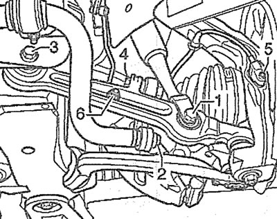
2.9. Unscrew the bolt and disconnect the rod of the ground clearance sensor 6 from the lower support arm:
2 - bolt for fastening the stabilizer bar hose to the rack
3 - support arm mounting bolt
4 - anti-roll bar mounting bolt
5 - ABS sensor mounting bolt
10. Unscrew bolt 1 securing the lower support of the shock absorber strut to the support arm (see illustration 2.9).
11. Disconnect plug 2 (see illustration).
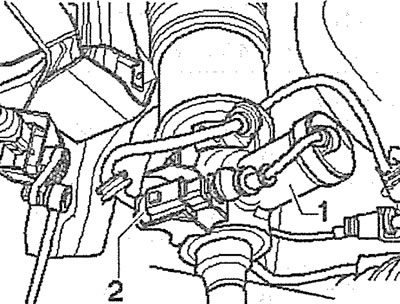
2.11. Disconnect plug 2
12. Unscrew the mounting bolts of the expansion tank of the cooling system (see arrow in illustration), remove the tank and move it to the side without disconnecting the hoses from it. Remove the fairing box.
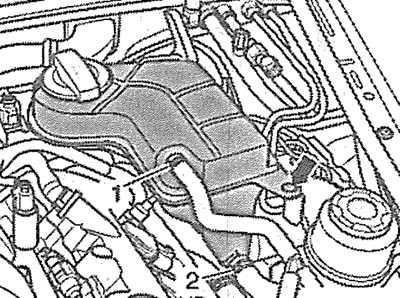
2.12. Unscrew the bolts securing the expansion tank of the cooling system (see arrow), remove the tank and move it to the side: 1 and 2 - clamps for fastening the hoses to the pipes on the tank
13. Remove the rubber bushing on the shock absorber strut and upper control arms support bracket (see arrow in illustration).
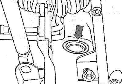
2.13. Remove the rubber bushing on the shock absorber strut and upper arm support bracket (see arrow)
14. Carefully unscrew nuts 1 securing the upper shock absorber strut support to the support bracket (see illustration).
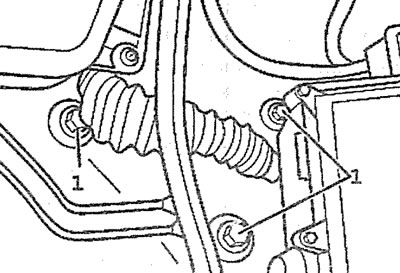
2.14. Carefully unscrew nuts 1 securing the upper support of the shock absorber strut to the support bracket
15. Remove the shock absorber strut by lowering it down.
Installation
16. Fix the shock absorber support bracket to the body by inserting the centering bushings into the corresponding holes.
17. Install the lower shock absorber strut support fork onto the control arm, insert the bolt and screw on the new nut 1. Tighten the nut to a final torque of 90 Nm only after the vehicle has been installed on the wheels.
18. Screw in the bolts securing the support bracket to the body (see illustration). Tightening of bolts is performed in the sequence of their numbering.
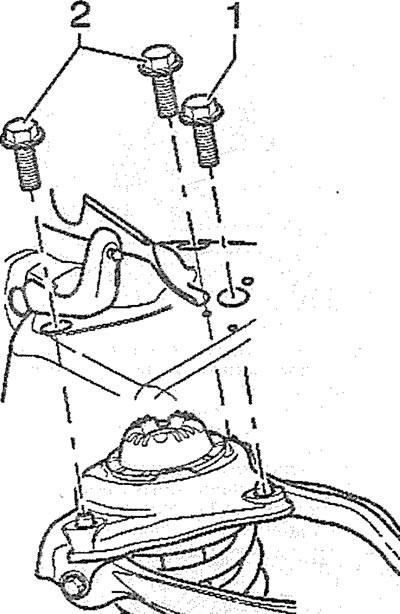
2.18. Tightening of the shock absorber strut support bracket mounting bolts is performed in the sequence of their numbering
19. Insert the pins 2 of the ball joints of the upper arms into the holes on the steering knuckle 3, press them in until they stop using a suitable puller, insert the tightening bolt and screw the nut 1 onto it (see illustration).
2.19. Insert the pins 2 of the ball joints of the upper arms into the holes on the steering knuckle 3, press them in until they stop using a suitable puller, insert the tightening bolt and screw the nut 1 onto it
Caution! Tightening the nut to the final torque should be performed after the vehicle has been installed on the wheels.
The installation of the remaining dismantled components is carried out in the reverse order of their removal.
Attention! After completing the work, the air suspension should be brought to the working position by pumping gas, the pressure of which should be within 3.5-4.5 bar. New air struts are supplied with a minimum pressure, so they should be pumped up.