
This ensures a reduction in the force required both to brake the wheels and to increase their rotation speed. The guide levers are mounted on hydraulic supports that provide wheel damping during movement.
The subframe, which serves as a support for the power unit, is connected to the front wheel suspension. The anti-roll bar is attached to the subframe. The 25 mm thick eccentric spacer bushings marked "B" are installed on the supports attaching the subframe to the body. On the front supports, the protrusion of the bushings faces the direction of travel of the car, and on the rear ones - against the direction of travel. Before dismantling the bushings, they and their mounting places should be marked (see illustration 1.0).
The front part of the subframe is connected by a cross brace, which is designed to increase its rigidity (see illustration 1.0a).
The front suspension shock absorbers are pneumatic, which provides four-level ground clearance (see illustration 1.0b).
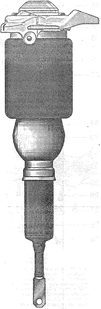
1.0b. Front suspension air strut
The upper support of the shock absorber strut is attached to the support bracket of the upper arms, and the lower one is attached to the supporting arm (see illustration 1.0v).
Torque is transmitted to the front wheels through two half-axles connected to the wheels and the main transmission by constant velocity joints.
Attention! Before performing repair work on the suspension, the clearance should be returned to the standard position and its regulator should be disconnected.
Optimal driving characteristics and minimal tire wear are achieved only with correct wheel alignment. If tire wear is abnormal and the vehicle is unstable on the road, you should immediately contact a workshop to check and set the wheel alignment. Independent checking and setting of wheel alignment without special equipment is impossible.
Attention! Welding and straightening work on the load-bearing and guide elements of the front suspension is prohibited. When carrying out repair work, always replace self-locking nuts, as well as rusted bolts and nuts with new ones.
[The original version of the article is posted on the website: AUDIMANUAL.ru]