
Table of contents: Steering rods, control arm, axle… ↓ Removal and installation the dust… ↓ Brake linings: checking thickness ↓
Steering rods, control arm, axle joint, guide arm and drive shafts on the front and rear axles: check for play, fastening and protective boots
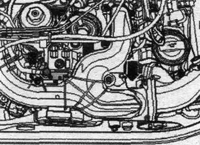
This check is carried out with the vehicle raised (wheels in suspension). Check for play by shaking the steering rods and wheels. There should be no visible or noticeable play. Check all protective covers of car "2" for damage and correct position; use a mirror if necessary. Damage to protective covers is usually determined by the presence of grease coming out.
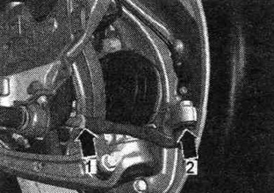
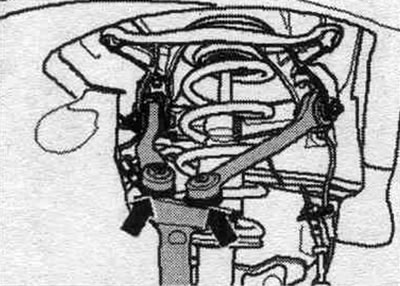
All levers: Check all protective covers of the "arrows" for damage and correct position; use a mirror if necessary.

Damage to protective covers is usually determined by the presence of grease coming out. There should be no visible or noticeable play.
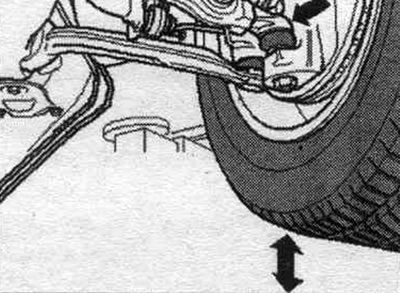
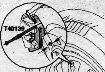
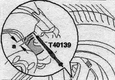
Support arms: With the wheels raised, check the movement of the wheel hub relative to the support arm. Wheel hub movement relative to the support arm is determined by repeatedly raising and lowering the wheel manually. If visible or noticeable play is observed when raising and lowering the wheel and moving the hub, the support arm must be replaced.
Drive shaft seals: Check the inner and outer axle shaft seals for damage and correct position, rotate the wheel if necessary. When turning the front wheels, cracks are visible at the very beginning of their formation. Damage to protective covers is usually determined by the intensely protruding grease.
Removal and installation the dust filter
Note: The cabin filter is available in different designs (with and without activated carbon filter element). Vehicles with the Comfort version of the air conditioning system are currently equipped with a cabin filter with an activated carbon filter element, while vehicles with the Basic version of the air conditioning system are currently equipped with a cabin filter without an activated carbon filter element. Clean the area around the dust filter in the air conditioner niche before installing the new filter. On vehicles equipped for driving instruction, it is necessary to remove (if available) duplicate pedals (depending on the version, the duplicate pedals have service connectors for training equipment).
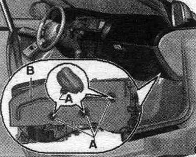
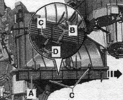
Move the front passenger seat to its rearmost position. Remove screw clip "A" and take out soundproofing mat "B." Cover the floor mat in the area under the cabin filter with paper.
Loosen latches "B", slide cover "A" in the direction of arrow "arrow" and remove it. Cover "A", if the latches "B" no longer hold it, can be secured with screws "D" at the mounting points "C".
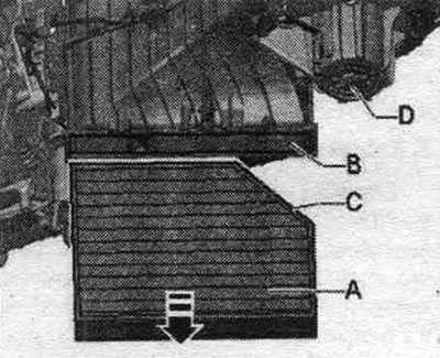
Remove cabin filter "A" from niche "B" of the air conditioner.
Installation
Installation in reverse order. Clean the air conditioner above niche "B" (for example, with a vacuum cleaner) after removing filter "A", install cabin filter "A" with the correct side up (bevels "C" facing the intake fan "D"). The flow direction for cabin filter "A" used in this vehicle is not specified.
Manufacturer's plate, vehicle identification number (VIN)
A. Nameplate
Attaches only to the right shock absorber cup.
B. Vehicle identification number
It is stamped on the top of the right side member of the wheel arch next to the expansion tank.
Vehicle data plate
It is located in the customer's service booklet, as well as in the spare tire well or on the bottom of the trunk. The sticker contains the following vehicle information.
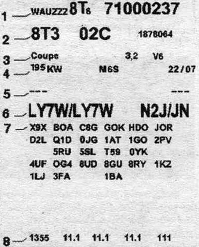
1. Vehicle identification number (VIN). 2. Vehicle type code number/Manufacturer. Control unit code. 3. Declared type. 4. Engine power/Emission standard/Gearbox. 5. Engine and gearbox letter designations (data is not available for certain countries). 6. Paint finish code/Interior trim codes. 7. Additional equipment codes. 8. Kerb weight/consumption/toxicity data (there is no data for some countries).
Abbreviated letter designation and engine number
Note: The "Engine code" is also indicated on the vehicle data plate in the service booklet and in the spare wheel well or on the luggage compartment floor mat. In addition, a sticker with the "engine letter designation" and "its serial number" is placed on the timing belt guard.
4-cylinder TFSI petrol engines
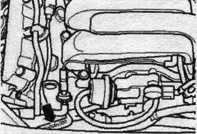
The engine number ("abbreviated engine letter designation" and "serial number") is located at the front of the engine/gearbox connection.
Decoding the vehicle identification number
| WAU | ZZZ | 8K | Z | 7 | А/N | 121 321 |
| Manufacturer's mark | Fill sign | Type | Fill sign | Model year 2007 | Manufacturing enterprise | Serial number |
V6 3.0L TFSI petrol engines; 3.2 L FSI
The engine number ("letter designation" and "its serial number") are stamped on the cylinder block, with an "arrow" on the left.
4-cyl. TDI engines
The engine number is located at the front of the engine/gearbox connection.
V6 TDI engines
The engine number is stamped on the cylinder block "arrow".
Brake linings: checking thickness
To determine the thickness of the lining, the moving ring should be moved until it stops in the direction of the measuring tip, then pass the measuring tip of the feeler gauge through the wheel rim and rest it against the brake. disk, then evenly insert the feeler gauge in the direction of the brake. pads so that the feeler gauge rests against the rear brake plate. linings. After this, remove the dipstick and read the readings from the scale marked with a special braking symbol. When removing the dipstick, make sure the sliding ring does not move, otherwise the results will be incorrect! The second scale marked on the dipstick (tire symbol), can be used to determine the profile thickness of a tire.
Disc brake pads, front
a. Thickness of the pads, including the back and damping plate. Wear level: 7.
Disc brake pads, rear
Wear level: 7.
Attention! Thickness of the overlay (including the back plate) with wear grade 7 on the front and rear axles (value on the dipstick scale) indicates that the linings have reached the wear limit and should be replaced (repair work). In some cars, due to the geometry of the wheel disk (accessories) the feeler gauge may not reach through the hole in the brake wheel disc. disc or lining, in this case proceed as follows. Visually determine the thickness of the outer brakes. overlays (using a flashlight through a hole in the wheel rim). Visually determine the thickness of the inner brakes. overlays (using a flashlight and a mirror).
The original version is on the portal: AUDIMANUAL.ru