
Repair Chevrolet Repair Toyota Repair Honda Repair AvtoVAZ Repair Mercedes-Benz Repair BMW Repair Opel
Home  |  Contacts  |  Sitemap  |    
English Русский
Български
Беларускі
Український
Српски
Hrvatski
Română
Polski
Slovenský
Magyar
AudiManual.ru


  • AUDI 80
  • AUDI 100
  • AUDI A3
  • AUDI A4
  • AUDI A6
  • AUDI A8
  • AUDI Q
  • OTHER
  • ARTICLES
B8 (2007-2015) B7 (2004-2008) B6 (2000-2006) B6 (2000-2006, petrol) B5 (1994-2001) B5 (1994-2001, petrol)

Hood — removal, installation and adjustment (Audi A4 B8)

  • Home
  • Audi A4
  • B8 (2007-2015)
  • Body
  • Exterior
  • Hood — removal, installation and adjustment
            0
Table of contents: Hood ↓ Removal and installation the hook ↓ Removal and installation the hood… ↓ Removal and installation the hood… ↓ Removal and installation a gas strut ↓ Removal and installation the seal ↓ Hood release cable with sheath ↓ Removal the drive lever ↓

Hood
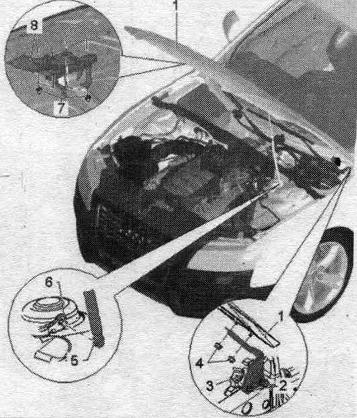


1. Hood: removal: remove the gas strut from the hood, unscrew the nuts «4» on the upper hinge of…

1. Hood: removal: remove the gas strut from the hood, unscrew the nuts "4" on the upper hinge of the hood, remove the hood; installation: in reverse order.; adjustment: Align the hood between the fenders, adjust the height of the hood above the bottom of the hood lock, align the hood relative to the fenders using stops.
2. Bolts: 21 Nm.
3. Trunk hinge: For removal and installation, the hood must be removed or securely supported; removal: remove the gas strut, unscrew bolts "2" and nuts "4"; installation: in reverse order.
4. Nut: 21 Nm.
5. Gas strut: the gas shock absorber pipe is installed on the body.
6. Ball pin: 21 Nm.
7. Nut: 8 Nm.
8. Hook.


Removal and installation the hook
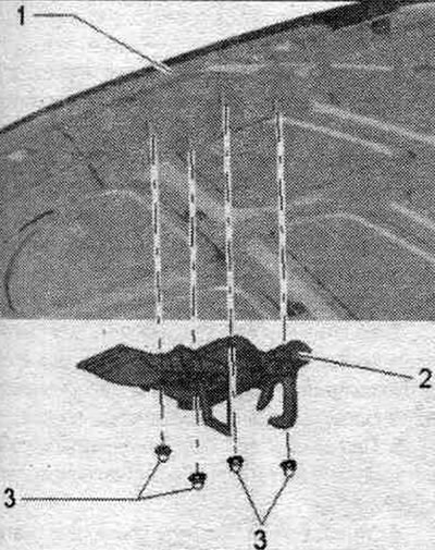


Removal and installation the hook


Unscrew the nuts and remove the locking hook.


Removal and installation the hood lock
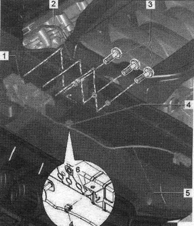


1. Trunk lock: detach the upper bumper cover and press it to the side, disconnect the lid lock…

1. Trunk lock: detach the upper bumper cover and press it to the side, disconnect the lid lock cable on the coupling, disconnect the plug connector, unscrew screws "1" and "2". For per. hood height, the hood lock moves up or down.
2. Radiator frame.
3. Bolt: 11 Nm.
4. Clamp: attach the clamp with el. with a wire to the tongue on the radiator frame.
5. Electrical wire of the hood lock.
6. Overlay.


Hood gap dimensions
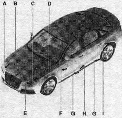


Dimension A = 5.0 mm. Dimension B = 4.5 mm. Dimension C = 5.0 mm. Dimension D = 3.0 mm. Dimension E…

Dimension A = 5.0 mm. Dimension B = 4.5 mm. Dimension C = 5.0 mm. Dimension D = 3.0 mm. Dimension E = 4.5 mm.


Removal and installation the hood hinge
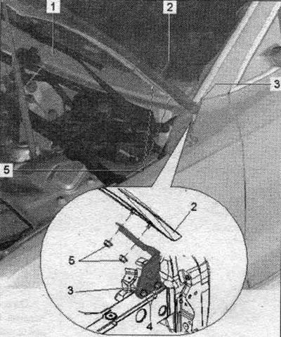


1. Gas strut: hang the gas strut tube from the hood side.

1. Gas strut: hang the gas strut tube from the hood side.
2. Hood.
3. Nut: 21 Nm.
4. Hood hinge: before removing the hinge, install the hood on supports and/or secure it from falling, remove the gas strut, unscrew bolts "4" and nuts "5"; installation: in reverse order.
5. Nut: 21 Nm.


Safety beam for per. height


Adjusting stops "2" are used for reg. lids by height.
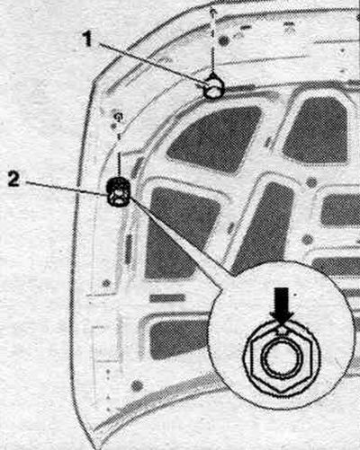
Adjusting stops «2» are used for reg. lids by height.


Adjusting stops "2" must be in contact with the radiator frame when the hood is closed. Rubber stops "1" serve as impact protection.

Replacing the hood protectors
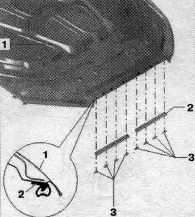


Additional protective stops. equipped with double-sided adhesive tape.

Additional protective stops. equipped with double-sided adhesive tape.

1. Lid.
2. Protective stop: to remove, remove the clip from the hood and remove the protective stop.
3. Clamp.


Hood trim
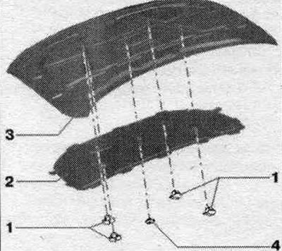


1. Mounting bracket.

1. Mounting bracket.
2. Hood trim: installation: first insert into the tabs at the rear. edge into the provided holes on the inner panel, insert the tabs on the front edge and on the side, the fastening clamps should be installed with a click, press the clamp.
3. Lid.
4. Clamp.


Removal and installation a gas strut
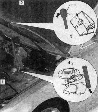


1. Gas strut: to remove, slightly lift the spring stopper «arrow» and remove the gas-filled shock…

1. Gas strut: to remove, slightly lift the spring stopper "arrow" and remove the gas-filled shock absorber from the ball-head bolt. When installing, ensure correct position: the gas-filled shock absorber tube must be suspended from the side of the cover.
2. Hood.
3. Ball pin: 21 Nm.


Support the hood or secure it to prevent it from falling. Using a small screwdriver, gently lift the spring retainer "arrow" and remove the gas-filled shock absorber "1" from the upper ball-head bolt "2". Repeat these steps for the lower ball-head bolt.
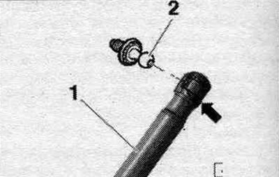
Support the hood or secure it to prevent it from falling. Using a small screwdriver, gently lift…


Installation


After completely removing the gas-filled shock absorber, ensure that it is positioned correctly during installation: the gas-filled shock absorber tube must be suspended from the body side. Press down on the gas strut and snap it onto the ball head bolts.


Removal and installation the seal
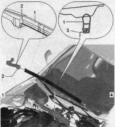


1. Water drain box seal: to remove, remove from the side of the body flange towards the rear;…

1. Water drain box seal: to remove, remove from the side of the body flange towards the rear; starting installation from the side, insert into the sealing profile with preliminary tension, gradually press the seal to the opposite side, also place the seal on the sealing profile on the opposite side, crimp the allowances along the front wall of the water drainage box.
2. Sealing profile on the right: to remove, detach from the body and remove from the side under the wing bracket; when installed, the foam element clips should snap into place in the body.
3. Front wall of the water drain box: install the windshield washer reservoir seal on the side.
4. Sealing profile on the left: to remove, detach it from the body and remove it from the side under the wing bracket: when installed, the clips of the foam element should snap into the body.


Hood release cable with sheath
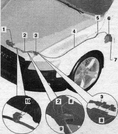


1. Trunk lock: to release the hood, move it up or down.

1. Trunk lock: to release the hood, move it up or down.
2. Hood lock cable: removal: disconnect the sheathed cable from the coupling, release the sheathed cable from bracket "7", pull the sheathed cable to the engine compartment; installation: in reverse order.
3. Cable pull clutch: Install the clutch clamp on the side of the radiator frame bracket "8"; before removing the radiator frame and when removing the release lever, disconnect the cable in the sheath.
4. Rear hood lock cable: a sheathed cable that goes to the drive lever in the car's interior.
5. Nozzle: When installing, ensure correct fit.
6. Drive lever.
7. Hood release lever: remove the hood release lever cover.
8. Radiator frame.
9. Electrical cable: Route the wire and hood lock cable through the radiator frame as shown in the figure
10. Clamp: clamp with el. install the wire onto the tongue on the radiator frame.


Cable traction coupling
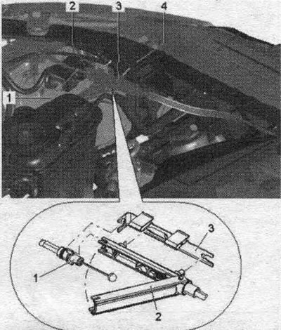


1. Cable pull, rear: cable pull to the drive lever; when removing, first pull it out from the…

1. Cable pull, rear: cable pull to the drive lever; when removing, first pull it out from the coupling in a backward direction.
2. Cable release clutch: To release, remove the clamp from the radiator frame and do not completely remove the cable release from the clamp; open the coupling and lift the front cable rod with the nipple out of the coupling.
3. Clamp: After installing the cable traction, install it on the side of the radiator frame.
4. Cable link, front: cable link to the hood lock.


Connecting the cable to the hood lock
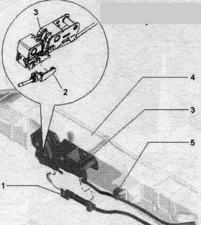


1. Sheathed cable, front: Insert the nipple for the cable pull into the actuator lever on the hood…

1. Sheathed cable, front: Insert the nipple for the cable pull into the actuator lever on the hood latch.
2. Cable in a sheath for right-hand drive vehicles.
3. Trunk lock: secure the cable guide into the housing at the bottom of the hood lock.
4. Radiator frame.
5. Clamp: clamp with el. install the wire onto the tongue on the radiator frame.


Installing a sheathed cable into the hood lock
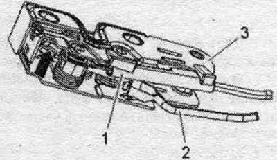


Installing a sheathed cable into the hood lock


Install the cable nipple in the sheath "2" into the drive lever "arrow" of the hood lock "3". Secure the cable in the sheath with the guide "1" at the bottom of the hood lock.

Removal the drive lever cover
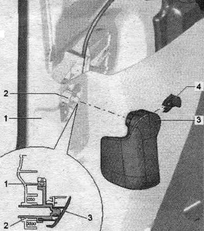


1. Lower trim of the «A» pillar.

1. Lower trim of the "A" pillar.
2. Drive lever cover: Before dismantling, remove only the cable traction in the clutch in the motor. compartment; release the fastening clamps from the drive lever, remove the trim from the side of the drive lever.
3. Drive lever.
4. Fastening bracket: press in fully with a click.


Removal the drive lever
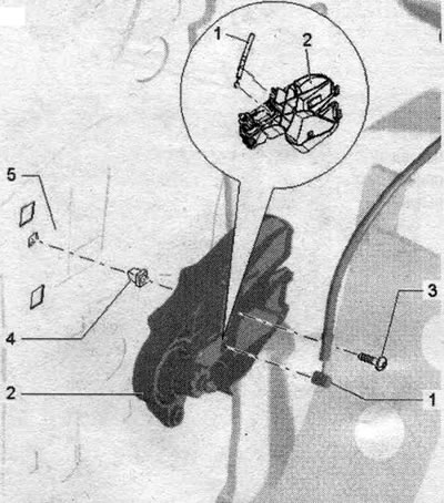


1. Cable in sheath: fix the cable stop in the sheath in the support bracket, as shown in the figure

1. Cable in sheath: fix the cable stop in the sheath in the support bracket, as shown in the figure
2. Drive arm support bracket: drive arm cover removed, "A" pillar cover, bottom, removed; unscrew bolts "3" and remove cable traction "1".
3. Bolts: 2 Nm.
4. Clamp.
5. Stand A.


Cable routing in the sheath in the cabin
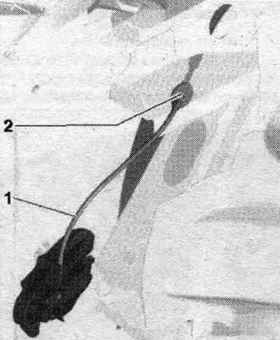


Cable routing in the sheath in the cabin


Place the cable in the sheath "1" toward the A-pillar, as shown in the figure. Attachment "2" should be pressed against the A-pillar, facing away from the passenger compartment.

Cable routing in a sheath in a motorcycle. compartment
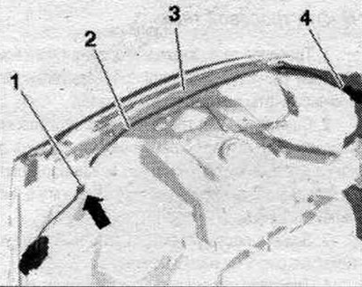


Cable routing in a sheath in a motorcycle. compartment


Place the cable in the sheath "2" coming from the passenger compartment into the motorcycle. compartment along the wing "3". Insert coupling "4" into the radiator frame.
The article was checked by auto expert Timur Bazhenov
This article is available at russian, bulgarian, belarusian, ukrainian, serbian, croatian, romanian, polish, slovak, hungarian

Share information:
Previous articles
Audi A4 B8: Exterior
Next articles

Front part of the body — wing
Front part of the body — radiator frame with attachments
Front of the body — radiator frame, service position
Sedan trunk lid — removal, installation and adjustment
Fuel filler flap — removal and installation
Front bumper — removal and installation
Front bumper — safety bar


Similar articles on other Audi car models:
Hood — removal, installation and adjustment Audi 80 B3 (1986-1991, petrol)
Hood Lock Cable — Removal, Installation and Adjustment Audi 100 C3 (1982-1990, diesel)
Removal, installation and adjustment of the hood Audi A3 Type 8L (1996-2003)
Hood Audi A6 C5 (1997-2004)
Steering column adjustment Audi A8 D2 (1994-2002)
Timing chain covers, valve 1 of timing phase adjustment «N205» Audi Q5 Type 8R (2008-2017)
Removal, installation and adjustment of the hood Audi A2 (1999-2005)
Link to this page in different formats


Visitor comments

No comments yet


How much will 34 + 12 =


A4(B8, 2007-2015) 
  • General information
  • Operating instructions
  • Power unit
  • Petrol engines 1.8 l
  • Petrol engines 1.8/2.0 l
  • Petrol engines 3.0 l
  • Petrol engines 3.2 l
  • Fuel system (petrol)
  • Diesel engines 2.0 l (CA*)
  • Diesel engines 2.0 l (CJCB)
  • Diesel engines 2.7/3.0 l
  • Diesel engines 3.0 l
  • Fuel system (diesel)
  • Transmission
  • Manual gearbox 0B1
  • Manual gearbox 0B2
  • Manual gearbox 0B3
  • Manual gearbox 0B4
  • Automatic transmission 0B5
  • Automatic transmission 0B6
  • Automatic transmission 0AW
  • All-wheel drive system
  • Chassis
  • Front suspension
  • Rear suspension
  • Brake system
  • Steering system
  • Body
  • Exterior
  • Interior
  • Seats
  • Doors, locks and windows
  • Security system
  • Heating and air conditioning
  • Electrical equipment
  • Audio system
  • Power devices
  • Equipment and devices
  • Lighting and lamps
  • Electrical circuits
 
A4(B7, 2004-2008) 
  • General information
  • Introduction to manual
  • Troubleshooting
  • Operating instructions
  • Maintenance
  • Power unit
  • Petrol engines 2.0 (ALT)
  • Petrol engines 2.0 (TFSI)
  • Petrol engines 1.8 (MPI)
  • Diesel engines
  • Cooling system
  • Air conditioner
  • Fuel and exhaust system
  • Ignition system
  • Starting and charging
  • Transmission
  • Clutch
  • Manual gearbox
  • Automatic gearbox
  • Drive shafts
  • Chassis
  • Brake system
  • Front suspension
  • Rear suspension
  • Steering
  • Body
  • Exterior
  • Interior
  • Electrical equipment
  • Equipment and devices
  • Lighting and signaling
  • Windscreen wipers and washers
  • Electrical diagrams
  • Electrical diagrams (since 2007)
 
A4(B6, 2000-2006) 
  • General information
  • Vehicle Description
  • User manual
  • Maintenance
  • Power unit
  • Gasoline engine
  • Diesel engine
  • Lubrication system
  • Cooling system
  • Supply system
  • Injection system
  • Exhaust system
  • Ignition and control
  • Transmission
  • Gear box
  • Clutch and drive shafts
  • Chassis
  • Brake system
  • Car suspension
  • Steering
  • Body
  • Heating and ventilation
  • Exterior (external elements)
  • Interior (internal elements)
  • Electrical equipment
  • Power devices
  • Lighting and appliances
  • Electrical circuits
 
A4(B6, 2000-2006, petrol) 
  • General information
  • Introduction to the guide
  • Car care
  • Power unit
  • Engine repair
  • Lubrication system
  • Cooling system
  • Injection and control system
  • Ignition system
  • Power and exhaust system
  • Transmission
  • Clutch and drive shafts
  • Car gearbox
  • Chassis
  • Suspension and wheels
  • Steering
  • Brake system
  • Body
  • Interior
  • Exterior
  • Electrical equipment
  • Equipment and devices
  • Lighting and signaling
  • Power devices
  • Electrical circuits
 
A4(B5, 1994-2001) 
  • General information
  • Introduction to the guide
  • Car care
  • Maintenance (gasoline)
  • Maintenance (diesel)
  • Power unit
  • Gasoline engines
  • Diesel engines
  • Engine overhaul
  • Cooling system
  • Fuel injection (gasoline)
  • Fuel system (diesel)
  • Exhaust system
  • Ignition system
  • Transmission
  • Clutch
  • Mechanical gearbox
  • Automatic gearbox
  • Drive shafts
  • Chassis
  • Brake system
  • Car suspension
  • Steering
  • Body
  • Exterior
  • Interior
  • Doors, locks and windows
  • Heating and ventilation
  • Electrical equipment
  • Power devices
  • Equipment and devices
  • Electrical circuits
 
A4(B5, 1994-2001, petrol) 
  • General information
  • Vehicle description
  • Maintenance
  • Power unit
  • Engine repair
  • Turbocharging
  • Exhaust system
  • Cooling system
  • Ignition system
  • Fuel system
  • Motronic injection system
  • MPI and MPFI injection system
  • Transmission
  • Clutch
  • Gearbox and shafts
  • Chassis
  • Steering
  • Car suspension
  • Brake system
  • Wheels and tires
  • Body
  • Heating and ventilation
  • Body parts
  • Electrical equipment
  • Fuses and relays
  • Power devices
  • Lighting and lamps
  • Tools and devices
  • Electrical circuits
 
AudiManual.ru © 2017-2026 · Mobile version · Feedback · Sitemap: EN BG BY UA RS HR RO PL SK HU · Site search · News and articles
80 B2 · 80 B3 petrol · 80 B3 · 80 B4 · 100 C3 diesel · 100 C3 petrol · 100 C3 · 100 C4 petrol · 100 C4 · A3 Type 8L · A4 B5 petrol · A4 B5 · A4 B6 petrol · A4 B6 · A4 B7 · A4 B8 · A6 C4 · A6 C5 · A6 C5 Allroad · A8 D2 · Q5 Type 8R · Q7 Typ 4L · Audi A2 ·
This site uses cookies 🍪. Click the button to accept this fact.