
2. Remove the electronics unit from the gutter.
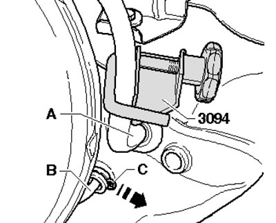
3. Clamp the supply hose (And in the illustration) clamp 3094, disconnect the hose from the brake fluid reservoir and plug the hose. Remove the seal from the engine compartment bulkhead above the feed hose connection tube. Slide the lock (C) and pull the tube and hose assembly (B) slightly.
10.3. Connections in the engine compartment
4. Remove the brake fluid reservoir mounting bolt (see illustration) and disconnect the low brake fluid level sensor connector.
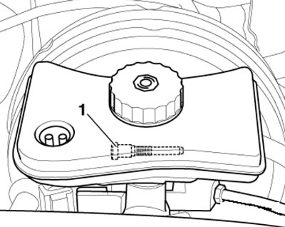
10.4. Brake fluid reservoir mounting bolt
Note: It is not necessary to remove the tank.
5. Remove the vacuum line leading to the brake booster (1 in the illustration) and unscrew the two bolts (arrows), tilting the brake fluid reservoir.
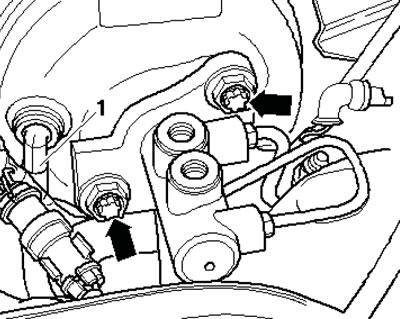
10.5. Vacuum hose and brake master cylinder mounting bolts
6. Remove the driver's storage compartment (see Chapter 11) and an eccentric spring (see illustration 7.2b). Separate the brake pedal from the brake booster.
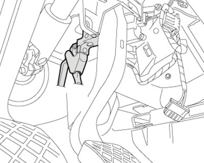
10.6. Brake pedal on the vacuum booster
7. Separate the steering column from the steering gear (And in the illustration, see Chapter 10), disconnect the connectors of the clutch pedal sensor (1), brake light D/W (2) and accelerator pedal module (3). If equipped, disconnect the connector of the engine start enable sensor. Loosen the bracket bolt (B) and remove the pedal assembly.
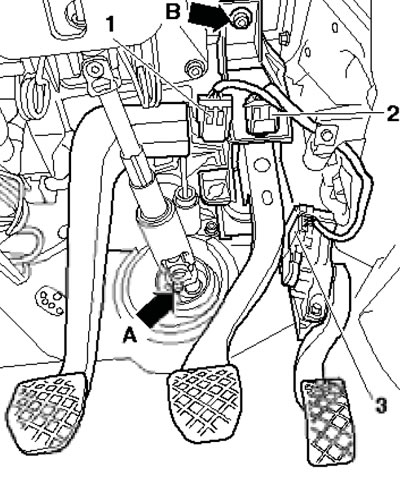
10.7. Sensor connector
8. Separate the master cylinder rod from the clutch pedal. To do this, squeeze the sides of the retainer with VAG1922 pliers and separate the clutch pedal from the master cylinder (see illustration).
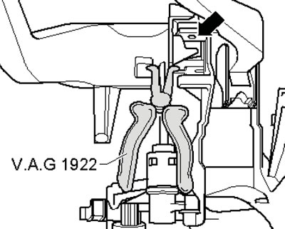
10.8. Separating the master cylinder rod from the pedal
9. Separate the retainer (1 in the illustration), remove the clutch pedal (2), unscrew the bolts (3) and remove the master cylinder (4).
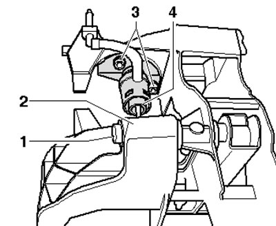
10.9. Removing the clutch master cylinder
10. Installation is carried out in the reverse order of dismantling the components.
[The original version is on the portal: AudiManual]