
Repair Chevrolet Repair Toyota Repair Honda Repair AvtoVAZ Repair Mercedes-Benz Repair BMW Repair Opel
Home  |  Contacts  |  Sitemap  |    
English Русский
Български
Беларускі
Український
Српски
Hrvatski
Română
Polski
Slovenský
Magyar
AudiManual.ru


  • AUDI 80
  • AUDI 100
  • AUDI A3
  • AUDI A4
  • AUDI A6
  • AUDI A8
  • AUDI Q
  • OTHER
  • ARTICLES
B8 (2007-2015) B7 (2004-2008) B6 (2000-2006) B6 (2000-2006, petrol) B5 (1994-2001) B5 (1994-2001, petrol)

Clutch — General Information (Audi A4 B7)

  • Home
  • Audi A4
  • B7 (2004-2008)
  • Transmission
  • Clutch
  • Clutch — General Information
            0
The clutch is designed to break the power connection between the engine and the manual transmission when shifting gears, and, thanks to the friction connection, ensures a smooth transfer of torque to the chassis at the start of movement.

The clutch mechanism consists of a pressure and driven disc (see illustration 7.1). A hydraulic clutch drive is used, consisting of a master and slave cylinder, pipelines, a clutch pedal and a clutch release mechanism.
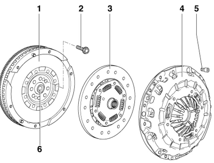
7.1 Clutch Mechanism Components 1. 2-mass flywheel; 2. Bolt, subject to replacement; 3. Slave disk;…

7.1 Clutch Mechanism Components 1. 2-mass flywheel; 2. Bolt, subject to replacement; 3. Slave disk; 4. Pressure disc; 5. Bolt, 22 Nm; 6. Needle bearing


The pressure plate is bolted to the flywheel, which is connected to the engine crankshaft. Between the pressure plate and the flywheel is a driven disk, which is pressed against the flywheel by the release bearing of the slave cylinder. The driven disk is connected to the primary shaft of the manual transmission via a splined connection.

When the clutch pedal is depressed, the brake fluid from the common reservoir is transferred under pressure through the clutch master cylinder to the slave cylinder. The release bearing of the slave cylinder acts on the pressure plate. In this case, the driven plate is moved away from the flywheel and the power connection between the engine and the manual transmission is interrupted. In the released state, the pressure spring presses the bearing against the diaphragm spring of the pressure plate. This reduces wear on the clutch pressure bearing, since it does not accelerate to the engine speed when engaged. No adjustment of the clutch drive is required.


Each time the clutch is engaged and disengaged, the friction linings of the driven disk wear out as a result of the force applied. The driven disk is a wearing part, but its average service life is quite long and depends mainly on the engine load and driving style. Wear of the diaphragm petals of the pressure disk is allowed up to half their thickness.
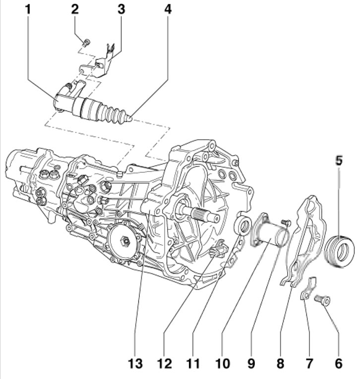
7.2a. Clutch release mechanism1. Slave cylinder; 2. Self-locking bolt for mounting cylinder 1, 23…

7.2a. Clutch release mechanism1. Slave cylinder; 2. Self-locking bolt for mounting cylinder 1, 23 Nm, subject to replacement; 3. Pipeline bracket; 4. Actuating rod; 5. Thrust bearing; 6. Self-locking bolt, 25 Nm, subject to replacement; 7. Leaf spring; 8. Clutch release lever; 9. Bolts, 3 pcs., 15 Nm; 10. Guide bushing; 11. Input shaft seal of the manual transmission; 12. Intermediate piece; 13. Manual transmission
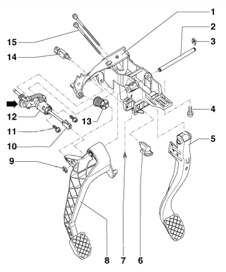

7.2b. Clutch pedal and master cylinder assembly 1. Pedal bracket; 2. Pedal axle; 3. Retainer; 4.…

7.2b. Clutch pedal and master cylinder assembly 1. Pedal bracket; 2. Pedal axle; 3. Retainer; 4. Bolt, 25 Nm; 5. Brake pedal; 6. Clutch pedal position sensor F36, must be replaced after removal; 7. Axle mounting bolt 2.5 Nm; 8. Clutch pedal; 9, 10. Retainer; 11. Bolt, 20 Nm; 12. Clutch master cylinder; 13. Eccentric spring, black side facing the pedal; 14. Clutch pedal sensor for engine start permission (uS models only), subject to replacement; 15. Bolt for fastening the brake master cylinder to the bracket, 25 Nm
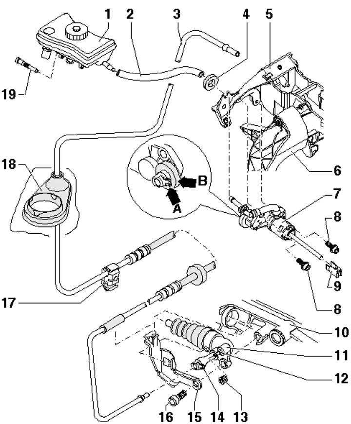


7.2c. Clutch hydraulic drive parts 1. Brake fluid reservoir; 2. Liquid supply hose to cylinder 7;…

7.2c. Clutch hydraulic drive parts 1. Brake fluid reservoir; 2. Liquid supply hose to cylinder 7; 3. Assembling hoses and tubes; 4. Compaction; 5. Bracket; 6. Clutch pedal; 7. Clutch master cylinder; 8. Bolt, 20 Nm; 9. Retainer; 10. Manual transmission; 11. Clutch slave cylinder; 12. Bleed valve, 4.5 Nm; 13. Dust cover; 14. Retainer; 15. Assembly bracket 3; 16. Self-locking cylinder mounting bolt 7, 25 Nm; 17. Retainer; 18. Compaction; 19. Tank mounting bolt 1


This article was copied from the website: AudiManual.ru
The article was checked by auto expert Timur Bazhenov
This article is available at russian, bulgarian, belarusian, ukrainian, serbian, croatian, romanian, polish, slovak, hungarian

Share information:
Previous articles
Audi A4 B7: Clutch
Next articles

Removal and installation the clutch basket, reinstalling the…
Removal and installation the clutch master cylinder


Similar articles on other Audi car models:
Clutch specifications Audi 80 B3 (1986-1991, petrol)
Clutch specifications Audi 100 C3 (1982-1990, diesel)
Changing the oil in the Haldex clutch of all-wheel drive models Audi A3 Type 8L (1996-2003)
Clutch drive disc Audi A6 C5 (1997-2004)
General information about the clutch Audi A8 D2 (1994-2002)
Removal the clutch pedal Audi Q5 Type 8R (2008-2017)
Clutch pedal assembly — design description Audi A2 (1999-2005)
Link to this page in different formats


Visitor comments

No comments yet


How much will 35 + 37 =


A4(B8, 2007-2015) 
  • General information
  • Operating instructions
  • Power unit
  • Petrol engines 1.8 l
  • Petrol engines 1.8/2.0 l
  • Petrol engines 3.0 l
  • Petrol engines 3.2 l
  • Fuel system (petrol)
  • Diesel engines 2.0 l (CA*)
  • Diesel engines 2.0 l (CJCB)
  • Diesel engines 2.7/3.0 l
  • Diesel engines 3.0 l
  • Fuel system (diesel)
  • Transmission
  • Manual gearbox 0B1
  • Manual gearbox 0B2
  • Manual gearbox 0B3
  • Manual gearbox 0B4
  • Automatic transmission 0B5
  • Automatic transmission 0B6
  • Automatic transmission 0AW
  • All-wheel drive system
  • Chassis
  • Front suspension
  • Rear suspension
  • Brake system
  • Steering system
  • Body
  • Exterior
  • Interior
  • Seats
  • Doors, locks and windows
  • Security system
  • Heating and air conditioning
  • Electrical equipment
  • Audio system
  • Power devices
  • Equipment and devices
  • Lighting and lamps
  • Electrical circuits
 
A4(B7, 2004-2008) 
  • General information
  • Introduction to manual
  • Troubleshooting
  • Operating instructions
  • Maintenance
  • Power unit
  • Petrol engines 2.0 (ALT)
  • Petrol engines 2.0 (TFSI)
  • Petrol engines 1.8 (MPI)
  • Diesel engines
  • Cooling system
  • Air conditioner
  • Fuel and exhaust system
  • Ignition system
  • Starting and charging
  • Transmission
  • Clutch
  • Manual gearbox
  • Automatic gearbox
  • Drive shafts
  • Chassis
  • Brake system
  • Front suspension
  • Rear suspension
  • Steering
  • Body
  • Exterior
  • Interior
  • Electrical equipment
  • Equipment and devices
  • Lighting and signaling
  • Windscreen wipers and washers
  • Electrical diagrams
  • Electrical diagrams (since 2007)
 
A4(B6, 2000-2006) 
  • General information
  • Vehicle Description
  • User manual
  • Maintenance
  • Power unit
  • Gasoline engine
  • Diesel engine
  • Lubrication system
  • Cooling system
  • Supply system
  • Injection system
  • Exhaust system
  • Ignition and control
  • Transmission
  • Gear box
  • Clutch and drive shafts
  • Chassis
  • Brake system
  • Car suspension
  • Steering
  • Body
  • Heating and ventilation
  • Exterior (external elements)
  • Interior (internal elements)
  • Electrical equipment
  • Power devices
  • Lighting and appliances
  • Electrical circuits
 
A4(B6, 2000-2006, petrol) 
  • General information
  • Introduction to the guide
  • Car care
  • Power unit
  • Engine repair
  • Lubrication system
  • Cooling system
  • Injection and control system
  • Ignition system
  • Power and exhaust system
  • Transmission
  • Clutch and drive shafts
  • Car gearbox
  • Chassis
  • Suspension and wheels
  • Steering
  • Brake system
  • Body
  • Interior
  • Exterior
  • Electrical equipment
  • Equipment and devices
  • Lighting and signaling
  • Power devices
  • Electrical circuits
 
A4(B5, 1994-2001) 
  • General information
  • Introduction to the guide
  • Car care
  • Maintenance (gasoline)
  • Maintenance (diesel)
  • Power unit
  • Gasoline engines
  • Diesel engines
  • Engine overhaul
  • Cooling system
  • Fuel injection (gasoline)
  • Fuel system (diesel)
  • Exhaust system
  • Ignition system
  • Transmission
  • Clutch
  • Mechanical gearbox
  • Automatic gearbox
  • Drive shafts
  • Chassis
  • Brake system
  • Car suspension
  • Steering
  • Body
  • Exterior
  • Interior
  • Doors, locks and windows
  • Heating and ventilation
  • Electrical equipment
  • Power devices
  • Equipment and devices
  • Electrical circuits
 
A4(B5, 1994-2001, petrol) 
  • General information
  • Vehicle description
  • Maintenance
  • Power unit
  • Engine repair
  • Turbocharging
  • Exhaust system
  • Cooling system
  • Ignition system
  • Fuel system
  • Motronic injection system
  • MPI and MPFI injection system
  • Transmission
  • Clutch
  • Gearbox and shafts
  • Chassis
  • Steering
  • Car suspension
  • Brake system
  • Wheels and tires
  • Body
  • Heating and ventilation
  • Body parts
  • Electrical equipment
  • Fuses and relays
  • Power devices
  • Lighting and lamps
  • Tools and devices
  • Electrical circuits
 
AudiManual.ru © 2017-2026 · Mobile version · Feedback · Sitemap: EN BG BY UA RS HR RO PL SK HU · Site search · News and articles
80 B2 · 80 B3 petrol · 80 B3 · 80 B4 · 100 C3 diesel · 100 C3 petrol · 100 C3 · 100 C4 petrol · 100 C4 · A3 Type 8L · A4 B5 petrol · A4 B5 · A4 B6 petrol · A4 B6 · A4 B7 · A4 B8 · A6 C4 · A6 C5 · A6 C5 Allroad · A8 D2 · Q5 Type 8R · Q7 Typ 4L · Audi A2 ·
This site uses cookies 🍪. Click the button to accept this fact.