
Fuel pump. An elastically suspended submersible pump, installed directly in the tank. The pump is surrounded by a reservoir with a net, which ensures the supply of fuel even if the fuel is strongly pumped (for example, when turning). The pump has an electric drive and in a petrol engine it forms a single unit together with the sensor for the fuel gauge.
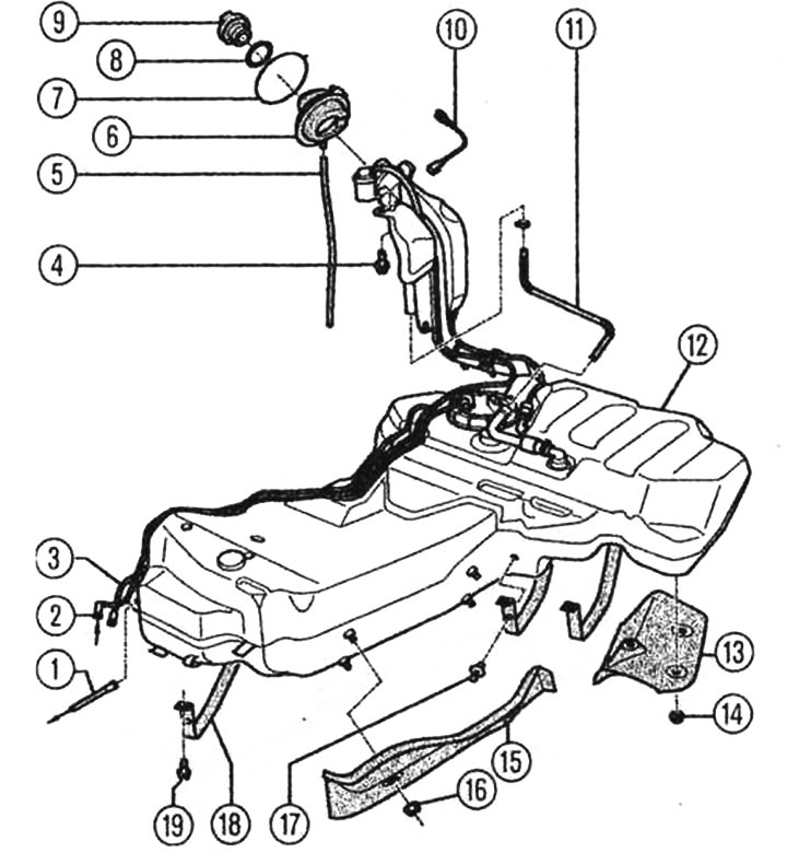
Fuel tank with parts mounted on it: 1 - fuel supply line from the fuel filter to the engine, 2 - fuel return line from the engine, 3 - air bleed line to the activated carbon tank, 4 - 23 Nm screw for fastening the filler neck and connecting to the housing, 5 - overflow hose, 6 - rubber cap, 7 - borrowed ring, 8 - sealing ring, 9 - cover, 10 - connection to the housing to remove static charges. 11 - air bleed line, 12 - fuel tank, 13 and 15 - heat shields, 14 and 16 - 2 Nm nut, 17 - spacer clamp, 18 - tension band, 19 - 23 Nm screw.
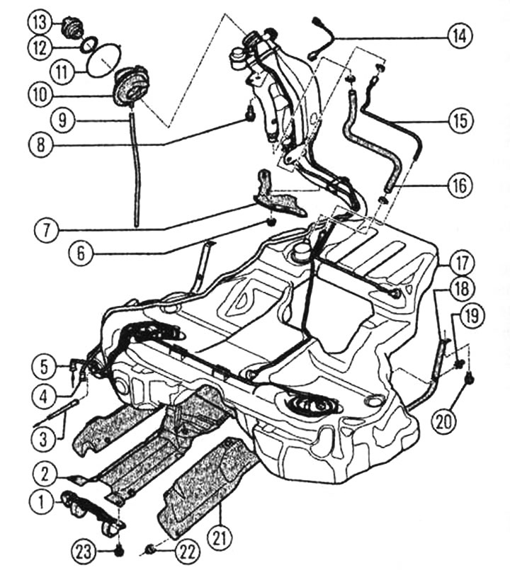
Fuel tank for all-wheel drive vehicles with parts mounted on it: 1 - bracket for the exhaust system, 2 - support plate, 3 - fuel feed line from the fuel filter to the engine, 4 - air bleed line to the activated carbon tank, 5 - fuel return line from the engine, 6 - 2 Nm nut, 7 - heat shield, 8 - 23 Nm screw for fastening the filler neck and connecting to the housing, 9 - overflow hose, 10 - rubber cap, 11 - clamping ring, 12 - sealing ring, 13 - cover, 14 - connection to the housing for removing static charges, 15 and 16 - air bleed line, 17 - fuel tank, 18 - clamping band, 19 - spacer clamp, 20 - 23 Nm screw, 21 - heat shield, 22 - 2 Nm nut, 23 - screw 23 Nm.
Fuel filter. The fuel filter filters out liquid and solid impurities. The filter is located on the lower part of the body, in front of the fuel tank (if you look in the direction of movement), it is built into the fuel supply line. The filter contains two filter elements on which contaminants are deposited.
Fuel level sensor. The fuel level sensor consists of a float and a potentiometer. As the fuel level decreases, the float drops and moves the potentiometer so that the potentiometer's resistance increases. As a result, the voltage on the fuel level indicator decreases and the indicator's pointer deflects toward "empty".
Excess fuel and gases are discharged directly into the fuel tank via a safety valve, which allows maintaining the appropriate pressure in the system even when the ignition is off.
Tank with activated carbon. This tank is located under the front right wheel housing. The vapors that are constantly formed in the fuel tank enter the activated carbon tank through the gravity and air release valve. The activated carbon absorbs these gases like a sponge. Depending on the engine load and the shaft speed, the control unit opens a vacuum hose with the help of an electromagnetic regeneration valve, which goes to the intake manifold. Fuel vapors are sucked from the activated carbon tank and fed for combustion.
The principle of operation of the activated carbon tank
During the so-called blowdown, the fuel vapors accumulated in the activated carbon are regenerated. To do this, under the effect of reduced pressure in the intake gas line, fresh air is sucked in through the ventilation opening, which is located at the bottom of the tank. The accumulated fuel vapors are dosed for combustion together with fresh air.
The air release valve prevents additional fuel vapors from being sucked out of the fuel tank when the valve is open and the pressure from the intake manifold is low. This valve primarily ensures that the activated carbon tank is emptied. If the air release valve is de-energized, for example due to a broken wire, it remains closed. In this case, the tank is not emptied.
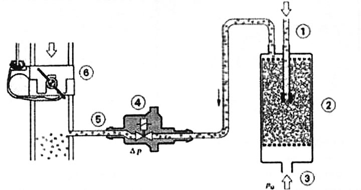
The principle of operation of the activated carbon tank: 1 - pipeline from the fuel tank to the activated carbon tank, 2 - activated carbon tank, 3 - fresh air, 4 - regeneration valve, 5 - pipeline to the intake gas line, 6 - throttle device with throttle valve.