
Table of contents: Clever ventilation system ↓ Rules of cleanliness ↓ The working principle of a jet pump ↓
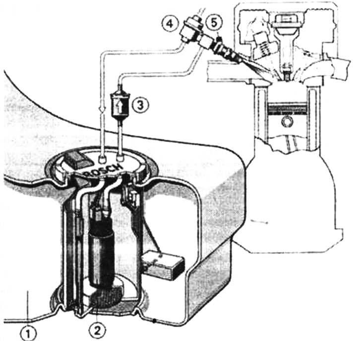
The fuel system of your car consists of five components: the fuel tank, the associated pipes, the fuel filter, the fuel pump and the petrol injection system, which was discussed in detail in one of the previous chapters. The fuel tank of the Audi A4 is made of plastic and has a capacity of 70 litres (quattro model: 66 liters). In the quattro model, the tank has a complex configuration, as it follows the shape of the differential. The fuel tank in all-wheel drive vehicles is divided into left and right chambers, so in this case, jet pumps are needed.
The fuel gauge sensor is installed at the top of the fuel tank (in the combination instrument), as well as the fuel supply and return line. These lines must withstand the high operating pressure of 3 bar. Therefore, these lines are made of particularly robust material and are secured at the factory using band clamps or clamps with a bolt and nut. For safety reasons, only original band clamps should be used when replacing. The use of screw clamps is not permitted!
Clever ventilation system
The pump supplies fuel through a system of pipes from the tank to the engine. A fuel filter is built into the supply pipe. Pipes for venting the tank are also connected to the filler neck. When fuel is poured into the tank, air is removed from the tank through this ingenious system. During driving, outside air rushes into the tank through this pipe depending on the amount of air consumed, so a vacuum does not occur in the tank.
Of course, the fuel tank's air outlet pipe doesn't just go outside. A special exhaust ventilation system ensures that the harmful fuel vapors are properly treated. The fuel vapors are diverted into a tank with activated carbon, and then added to the fuel intended for combustion.
Fuel recirculation system: 1 - fuel tank, 2 - fuel pump module, 3 - fuel filter, 4 - fuel supply pressure regulator, 5 - injector.
Rules of cleanliness
When working on the fuel supply and injection system, Audi recommends observing the following six rules:
- 1. The joints and adjacent parts must be thoroughly cleaned before loosening.
- 2. Place the removed parts on a clean stand and cover them. Do not use soaked rags!
- 3. If the repair will not be carried out immediately, carefully cover or close the open parts.
- 4. Install only clean parts. Remove parts from packaging immediately before installation. Do not use parts that have been stored unpackaged (for example, in toolboxes, etc.).
- 5. Do not work with compressed air when the system is open. If possible, do not move the vehicle.
- 6. Protect disconnected connectors from dirt and moisture; only dry connectors can be connected.
The working principle of a jet pump
On all-wheel drive models, the fuel tank is divided into a left and right chamber so that fuel from the left half of the tank can be supplied to the fuel pump module 8 (to the gasoline pump), which is located in the right half of the tank, a jet pump 1 is required. The second jet pump 7 is located in the right chamber, it improves the fuel supply to the gasoline pump.
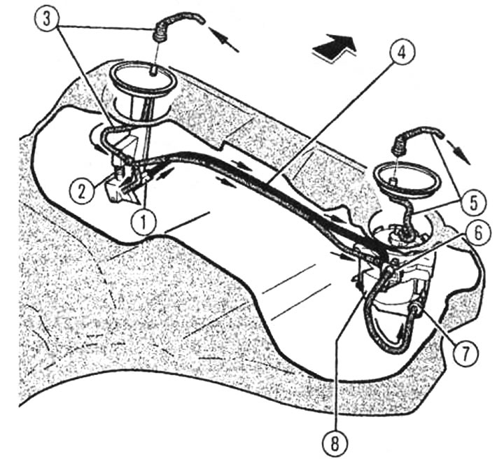
Only the jet pump located on the left side of the fuel tank 1 is removed. The pump located on the right 7 is an integral part of the fuel pump module and cannot be changed separately
The jet pumps operate according to a simple physical principle: the driving jet from the return line 3 in the jet pumps 1 and 7 passes through a nozzle and is therefore accelerated. Due to this acceleration, the adjacent fuel is set in motion, which is pumped into the fuel pump module. The right jet pump 7 supplies fuel directly to the module housing, and the left pump 1 - through a separate line 4. Through the tee 2, the fuel from the return fuel line is distributed to both jet pumps. The distributor 6 limits the pressure in the lines that go to the jet pumps to approximately one bar. Excess fuel is discharged through the line into the fuel pump module housing. The arrow in the figure indicates the direction of movement. The supply fuel line 5 is located on the fuel pump module.
The article was copied from the website: AudiManual.ru