
Table of contents: Is there ignition voltage? ↓ Visual inspection of the ignition… ↓ Is the voltage supply to the… ↓ Sources of malfunctions ↓ Checking the ignition coil ↓ Testing the final power stage ↓ Checking the Hall sensor ↓ Checking the ignition coils and… ↓ Checking ignition coils ↓ Testing the final power stage ↓ Checking the Hall sensor ↓ Checking the ignition coil ↓ Testing the final power stage ↓ Checking the engine speed sensor ↓ Checking the ignition timing sensor ↓ Knock sensor ↓
Anyone who wants to identify a defect in the ignition must act according to the system:
- Whether there is an ignition spark at all can be determined by simply checking the voltage.
- Current is supplied to the ignition/injection system via fuses 28, 29, 32 or 34 (depending on the engine model). If the ignition fails, check these fuses (chapter Electrical equipment).
- Careful visual inspection will often reveal the most common sources of failure (wires, connectors, voltage breakdowns).
- Only after this, check the ignition coil, Hall sensor, or engine speed sensor, or ignition timing sensor one by one.
- If all this was unsuccessful, have the workshop interrogate the computer.
Turn off the ignition by removing the connector on the output stages.
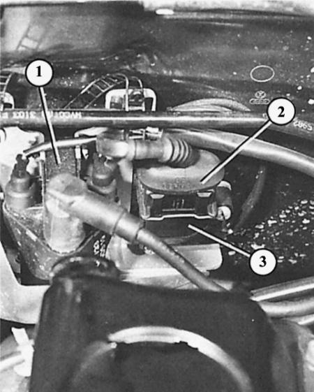
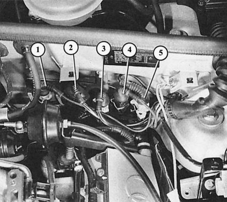
On the 1.6L four-cylinder engine, connector (2) is disconnected at the final stage (3) near the ignition coil (1).
In the four-cylinder turbo engine and in the six-cylinder engine, both connectors (arrows) on the final stage are disconnected.
Is there ignition voltage?
1. 74 kW engine: remove one of the wires on the spark plug, unscrew the spark plug.
2. Reconnect the high-tension wire to the spark plug and place it on the engine block so that it has reliable contact with the block. Even better, connect the threaded part of the spark plug to the engine with an auxiliary starting wire to ensure conductivity.
3. Have your assistant turn the engine over with the starter.
4. If powerful sparks jump on the spark plug electrodes, then there is ignition voltage, i.e. the ignition system is working. But the main adjustment of the distributor may be incorrect.
5. 92 kW engine: basically the same procedure as with the 74 kW engine, but needs to be checked (to make sure both coils are working) spark plugs for cylinders 1 and 2.
6. Leave the spark plugs for cylinders 3 and 4 installed.
7. Four-cylinder engine with a power of 110 kW: unscrew the ignition coil, unscrew the spark plug.
8. Reconnect the coil and spark plug and secure them to the engine so that the spark plug has contact with the ground and cannot be shaken off by the movement of the engine. This is achieved, for example, as follows: the threaded part of the spark plug is connected to the engine, ensuring conductivity, by means of the terminal of the auxiliary wire for starting it.
9. Otherwise, the same actions as for the 74 kW engine, if necessary, repeat the same on the remaining cylinders.
10. Six-cylinder engines: Basically the same procedure as for the 74 kW engine, but you need to check (to make sure all three coils are working) spark plugs for cylinders 1, 2 and 3.
11. For all engines: If there is no spark, try again with the spark plug of another cylinder. If there is still no spark, check the entire ignition system.
Here it is checked whether a spark appears in the ignition system at all. For reliability, the spark plug should be secured to the engine by means of a jumper cable to ensure conductivity. This is not shown here for the sake of clarity.
On the removed connector (2), it is checked relative to the ground (3) whether voltage is supplied to the final stage (1).
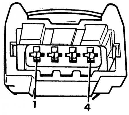
Open ignition distributor (there is a four-cylinder engine here)
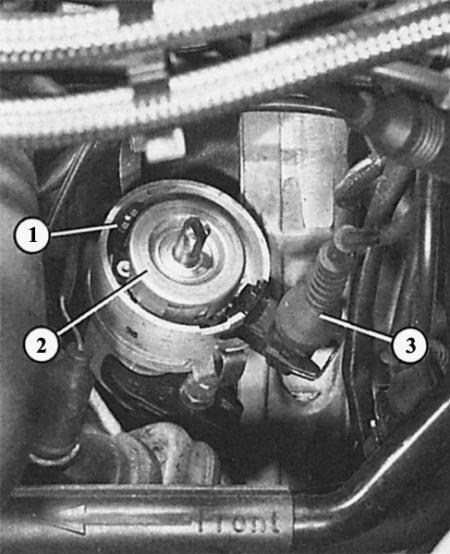
- 1 - Hall sensor;
- 2 - diaphragm rotor;
- 3 - Hall sensor connector.
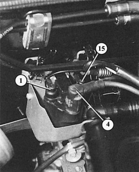
The ignition coil of the 1.6L four-cylinder engine is provided with the correct terminal designations
Visual inspection of the ignition system
1. Are all wires and connector contacts securely connected to the ignition coil, output stage, ignition/injection control unit and distributor (74 kW)?
2. Is it possible that one pin contact has shifted in the multi-pin connectors?
3. Is there any obvious damage to the wires?
4. Is the ignition coil's filler material squeezed out? Could it be faulty because of this?
5. Are there any cracks or burn marks from sparks on the ignition coil housing?
6. Additionally, check whether the high-voltage wires are securely fastened and whether the insulation is damaged. Modern ignition systems, due to high ignition voltages, react more sensitively to jumping sparks and creeping currents.
7. Is there any damage to the distributor cap (74 kW)? Pay particular attention to the inside.
8. Are all ignition system components clean and dry? Wet dirt can cause voltage breakdowns.
Tip: When taking the following measurements, please note that the measuring and control devices must be connected and disconnected only when the ignition is switched off. If the engine is repeatedly turned over by the starter without starting for testing and taking measurements, the wire connectors on the injection valves must first be disconnected.
Is the voltage supply to the ignition system ok?
Along with the complete failure of the ignition system due to lack of voltage, its insufficient supply can also cause significant disruptions in the operation of the system!
1. Are all fuses OK?
2. 74 kW engine: Disconnect the connector on the power output stage near the ignition coil.
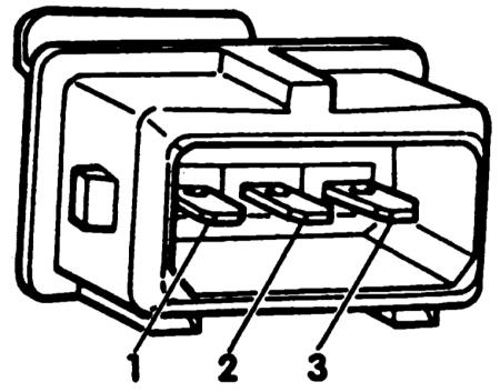
3. Connect the measuring device to the disconnected connector between contact 1 (terminal 15) and contact 3 (ground).
4. Turn on the ignition.
5. The device should show at least 11.5 V.
6. If it does not show any voltage at all or it is too low, then the defect lies in the wire to the ignition switch.
7. 92 kW engine: Remove the cylinder head cover, disconnect the connector at the final power stage on the ignition coil pack.
8. Connect the measuring device to the disconnected connector of the black/blue wire contact (this is average) and mass.
9. Turn on the ignition.
10. The device should show at least 11.5 V.
11. If it does not show any voltage at all or it is too low, then the defect lies in the wire to the ignition switch.
12. Four-cylinder engine with a power of 110 kW: remove the cylinder head cover, disconnect the connector on one of the ignition coils.
13. Connect the measuring instrument to the disconnected connector of the black/blue wire contact and to the contact of the brown/yellow wire (ground). These are the sockets of the connector 2 and 3.
14. Turn on the ignition.
15. The device should show at least 11.5 V.
16. If it does not show any voltage at all or it is too low, then the defect lies in the wire to the ignition switch.
17. Six-cylinder engine: Disconnect the white connector on the left side of the rear wall of the engine compartment (supply voltage to ignition coils), connect the measuring device between each of the three inputs of terminal 15 in turn (at the top of the connector) and mass.
18. Turn on the ignition.
19. The device should show at least 11.5 V.
20. If it does not show any voltage at all or it is too low, then the defect lies in the wire to the ignition switch.
21. For all engines: Measure the duration of -+ on the control unit relative to ground (red wire on 16-pin connector). Nominal value: battery voltage.
22. The same measurement on the black/white wire on the 16-pin connector of the control unit with the ignition on.
23. There, too, the device should show at least 11.5 V.
Sources of malfunctions
- The ignition switch is faulty (chapter Tools and instruments).
- There is no continuity in the wires between the ignition switch/central switching unit and the central switching unit/ignition coil or central switching unit/control unit. Check the wires and connectors according to the wiring diagram in the manual.
Checking the ignition coil
Four-cylinder engine 74 kW
1. Visual inspection of the ignition coil has already been carried out.
2. To check the resistance, turn off the ignition, disconnect all the wires on the ignition coil. We measure the primary and secondary windings of the coil.
3. Take measurements by connecting an accurate ohmmeter between the ignition coil terminals 1/- and 15/+.
4. Nominal value: 0.5-1.5 Ohm.
5. The next measurement is made between terminal 15 and 4 (4 = thick main high voltage wire socket).
6. The device should show 5–9 kOhm.
7. If the specified values are not obtained, replace the ignition coil.
8. These measurements cannot detect a short circuit between the windings. If, despite good measurement results, suspicion still falls on the ignition coil, you should have the dismantled coil checked at an automotive electrical equipment repair shop.
Testing the final power stage
Four-cylinder engine 74 kW
1. Checking the setting: Disconnect the connectors on the power output stage near the ignition coil.
2. Connect the measuring device to the removed connector between pin 2 (setting) and pin 3 (ground). Crank the engine with the starter. The device should show at least 2 V.
3. Check the voltage supply to the ignition system as already described.
4. Check the ignition coil.
5. If there is no spark in the ignition system, although no defects are found after performing the three mentioned checks, the source of the fault must be in the final power stage. In this case, replace the final power stage and the ignition coil together.
Checking the Hall sensor
Four-cylinder engine 74 kW
1. Disconnect all connectors on the injection valves.
2. Disconnect the connector on the power output stage near the ignition coil.
3. Functional check: bend back the rubber tip on the connected Hall sensor connector (on the side of the distributor – difficult to access) so that the contacts are accessible for measurement from behind.
4. Connect the LED indicator lamp to terminal 1 (green/white) wire and 2 (green/gray wire).
5. Have your assistant turn the engine over with the starter: the LED should flash, in which case the Hall sensor and the wire to it are OK.
6. If it does not blink, then check the supply wire: disconnect the connector from the Hall sensor, connect the voltmeter to terminal 1 (green/white wire) and to terminal 3 (green/purple wire) connector.
7. Turn on the ignition.
8. Look at the meter: it should show 4.5–5.5 V.
9. Now connect the voltmeter to terminal 2 (green/gray wire) and to terminal 3 (green/purple wire) connector.
10. Turn on the ignition. Look at the measuring device: it should show 4.3–5.2 V.
11. Result: If the LED indicator lamp does not flash, although the voltage readings are correct, the Hall sensor is faulty.
12. Voltage readings are not correct: no conductivity in the control unit connecting wire.
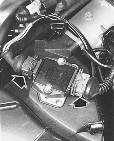
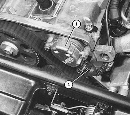
The final power stage (2) of the ignition coils of the 1.8 l 110 kW turbo engine is located on the air filter housing on the right side of the engine compartment.
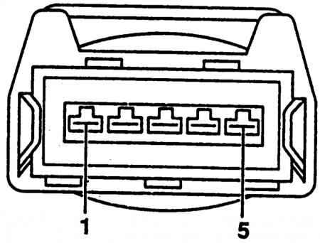
The figures show the location of the contacts of the four-pole connector ("3" in the photograph) and the five-pole connector ("1" in the photograph).
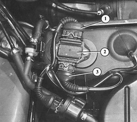
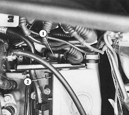
On a 1.8L four-cylinder engine, the Hall sensor is located on the left front of the engine. You can see:
- 1 - Hall sensor housing;
- 2 - connector.
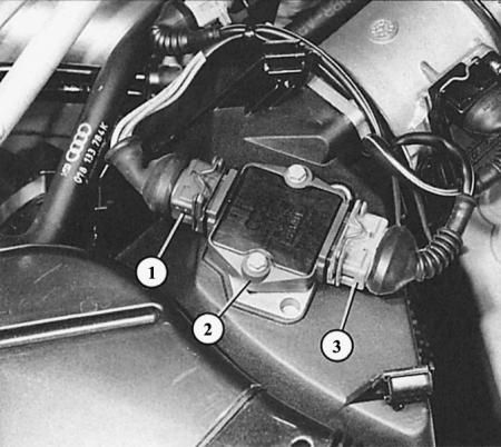
In a six-cylinder engine, the Hall sensor (1) is located at the rear of the left cylinder head (2).
Checking the ignition coils and final power stage
Engine 92 kW
1. Perform a visual inspection as described above.
2. Check the voltage supply as described above.
3. Disconnect all connectors on the injection valves.
4. Check the input signals: disconnect the ignition coil/power output stage connectors. Connect a diode test lamp to one of the outer terminals of the connector and measure against ground.
5. When turning the engine over with the starter, the lamp should flicker slowly.
6. Perform the same measurement on the opposite contact of the connector. The lamp there should also blink slowly.
7. If the LED indicator does not flash: the defect is in the supply wire, the control unit or one of the sensors in the control unit. Replace the entire assembly.
8. All measurements are OK, but there is no ignition spark: ignition coils/power output stage are faulty.
Checking ignition coils
Four-cylinder engine 110 kW
1. Disconnect all connectors on the injection valves.
2. First, check the ignition voltage (described above).
3. If there is no spark in any of the spark plugs, check the voltage supply to the ignition system (just as described).
4. If there is no spark in one spark plug, swap the coils: if the defect moves with the coil, then the cause is in this coil.
5. To be sure, swap the spark plugs again to eliminate the source of the fault.
6. If replacing the coils does not produce results, disconnect the connector on the ignition coil of the inoperative cylinder and measure the voltage in the connector.
7. Connect the test lead to both outer terminals of the ignition coil three-pin connector.
8. Turn on the ignition, the voltmeter should show 12 V. If there is no voltage, then look for a defect in the wire to the plus and minus.
9. Turn off the ignition.
10. Checking the pulses: connect the voltage indicator to contacts 2 and 3 of the connector.
11. Have your assistant operate the starter.
12. The LED should flicker.
13. If the voltage indicator LED does not blink: the supply wire, the final power stage, the control unit or one of the control unit sensors is faulty.
14. Turn off the ignition.
Testing the final power stage
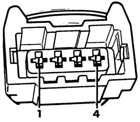
Four-cylinder engine 110 kW
1. Disconnect the connectors on all injection valves.
2. Disconnect the four-pole connector on the power output stage (under the cover on the air filter housing).
3. Connect one wire of the LED voltage indicator to ground.
4. Test 1: Apply the free lead of the voltage indicator to the contacts of the power output stage of pin 1, 2, 3 and 4 in turn.
5. Each time, your assistant turns the engine with the starter.
6. The voltage LED should flicker for all four measurements, in which case the output signal from the final power stage to the ignition coils is OK.
7. Reconnect the connector.
8. Disconnect the five-pin connector on the power output stage.
9. Test 2: This time, apply the free wire of the voltage indicator to the disconnected connector contacts 1, 2, 4 and 5, while your assistant turns the engine with the starter each time.
10. The voltage LED should flicker on all four pins, in which case the input signal to the power output stage is OK.
11. Test 3: Check if the ground connection at pin 3 of the five-pin connector is OK.
12. Result: If the input signal is OK with a working ground connection, but there is no output signal, then the power output stage is faulty.
13. If there is no input signal at all, then the cause of the malfunction is in the control unit (or in its sensors) or in the supply wire.
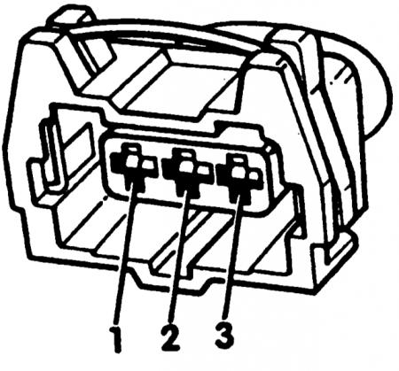
Checking the Hall sensor
1.8L four-cylinder engine and six-cylinder engine
1. Disconnect all connectors on the injection valves.
2. Bend back the rubber cap on the back of the Hall sensor connector (the connector remains connected).
3. Check with the LED voltage indicator whether there is voltage between terminal 1 and 3 of the connector (the terminals on the connector are marked) with ignition on (min 4 V).
4. If not, check the supply wire.
5. Connect the LED voltage indicator between terminal 2 and 3.
6. Have your assistant turn the engine over with the starter.
7. The voltage indicator LED should flicker slowly - the Hall sensor is OK.
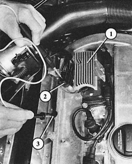
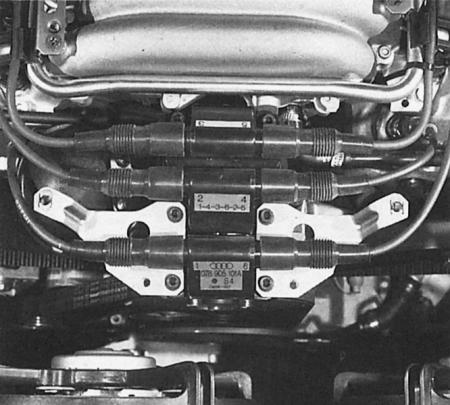
The power output stage (2) of the ignition coils in a six-cylinder engine is located on the air filter housing on the right side of the engine compartment.
The figures show the location of the contacts of the three-pole connector ("1" in the photograph) and the four-pole connector ("3" in the photograph).
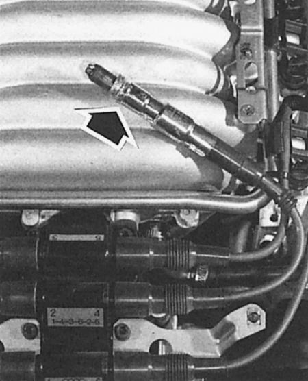
When electrically testing the ignition coil pack (six-cylinder engine) the measurements are taken, firstly, on the opposite sockets of the high-voltage wire, and secondly, on the three-pole connector of the final power stage at the rear left on the wall of the engine compartment. The installation position is shown in the photograph. The placement of the connectors is shown in the figure.
Pin connectors at the rear center of the engine compartment of a six-cylinder engine
- 1 - knock sensor II (blue);
- 2 - heating and lambda probe signal (probe on the left, black);
- 3 - ignition coils (lead wire, white);
- 4 - ignition timing sensor (black);
- 5 - engine speed sensor (gray).
Location of contacts of the engine speed sensor and ignition timing sensor connectors.
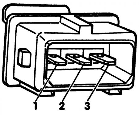
Checking the ignition coil
Six-cylinder engine
1. A visual inspection of the ignition coils has already been performed.
2. To check the resistance, disconnect all high voltage wires on the coils. We take measurements on the secondary winding of the coil.
3. Measure with an accurate ohmmeter between the spark plug wire sockets of cylinders 1 and 6 (1st coil). Nominal value: 9–14 kOhm.
4. Repeat the same measurement between the spark plug wire sockets of cylinders 2 and 4 (2nd coil), and also between the ignition wire sockets of the 3rd and 5th cylinders (3rd coil).
5. If everything is OK, then the secondary winding of the coils is measured.
6. Disconnect the white pin connector on the rear wall of the engine compartment (supply voltage to ignition coils), connect the measuring device of your choice to one of the three terminal 15 connectors (at the top of the plug connector).
7. Disconnect the three-pin connector on the power output stage (under the air filter cover), connect the second wire of the measuring instruments one by one to all three terminals in the connector.
8. Nominal value: 0.5–1.0 Ohm for all three dimensions.
9. If the specified values are not obtained, replace the ignition coil pack.
Testing the final power stage
Six-cylinder engine
1. Disconnect the connectors of all six injection valves.
2. Disconnect the three-pole connector on the power output stage (under the air filter cover).
3. Connect one wire of the LED voltage indicator to ground.
4. Test 1: Apply the free lead of the voltage indicator to the contacts of pin 1, 2 and 3 of the power output stage in turn.
5. Each time, your assistant turns the engine with the starter.
6. The voltage LED should flicker for all three measurements, in which case the output signal from the final power stage to the ignition coils is OK.
7. Reconnect the connector.
8. Disconnect the four-pole connector on the power output stage.
9. Test 2: Apply the free wire of the voltage indicator to the disconnected connector contacts 1, 2 and 4 one by one, while your assistant turns the engine with the starter each time.
10. The voltage LED should flicker on all four pins, in which case the input signal to the power output stage is OK.
11. Test 3: Check if the ground connection at pin 2 of the four-pole connector is OK.
12. Result: If the input signal is OK with a working ground connection, but there is no output signal, then the power output stage is faulty.
13. If there is no input signal at all, then the cause of the malfunction is in the control unit (or in its sensors) or in the supply wire.
Checking the engine speed sensor
Six-cylinder engine
The engine speed sensor is located on the flywheel ring gear. The pin connection of its wire is directed upward to a bracket on the rear wall of the engine compartment, so the measurement does not need to be carried out under the car.
1. Follow the wire route from the sensor to the bracket on the rear wall of the engine compartment, check the plug connectors and wire.
2. Electrical testing with a precise ohmmeter:
3. Disconnect the gray three-pin connector and connect an ohmmeter to the sensor wire between pin 1 and 2.
4. The ohmmeter should show about 1 kOhm, otherwise the sensor is faulty.
5. The third contact is the shielding wire.
6. To check the shielding, now connect the ohmmeter between pin 1 and 3, and then to pin 2 and 3.
7. The ohmmeter should show u Ohm, otherwise the sensor is faulty.
Checking the ignition timing sensor
Six-cylinder engine
Tips: Another check is to unscrew the sensor and clean its front side. Note: Never unscrew the sensor bracket, only the sensor itself.
The ignition timing sensor is mounted on the left rear directly on the crankcase housing. It is checked on the black three-pin plug connector in the bracket on the rear wall of the engine compartment.
The direct check is identical to the one done on the engine speed sensor. You just don't need to clean the front side.
There are no methods in the traditional sense to check the ignition/injection system control unit. But the defect is detected in the workshop by reading the computer that stores the faults.
Knock sensor
Knock sensor (starting with the 1.8-liter engine, two of them are installed) is checked by polling the computer. There are no other options for checking. Sometimes a defective knock sensor attracts attention with an intense ringing sound in the engine during acceleration. When installing a new knock sensor, be sure to take into account the correct tightening torque of the mounting bolt of 20 Nm.