



Table of contents: Hall sensor ↓ Speed sensor and ignition timing… ↓
Hall sensor
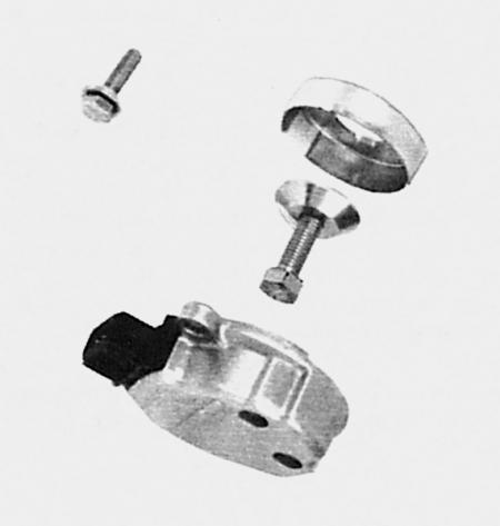
Disassembled Hall sensor of the engine with a working volume of 1.8 liters. The most important parts are the integrated Hall system (in a housing with a connector) and a diaphragm rotor.
In very simple terms, the Hall sensor switches the current to the ignition coil on and off (bypass through the control unit and the final stage). It is named after the Hall effect discoverer that is used in this sensor.
The Hall sensor consists of the following parts: a diaphragm rotor, for example, with four notches (depending on the number of cylinders), permanent magnet and the direct integral Hall system located opposite it. All this works like a light shutter, only here instead of light they work with electromagnetic radiation.
If the rotor diaphragm is in an electromagnetic field, the Hall sensor sends current to the control unit. When the diaphragm moves away from the air gap between the Hall integral system and the permanent magnet, the current does not flow to the control unit. These are signals for ignition. The Hall sensor is located:
- in a 74 kW engine under the distributor;
- in the 92 kW engine and in the 110 kW four-cylinder engine, at the front left on the cylinder head;
- in a six-cylinder engine, at the rear on the left cylinder head.
Speed sensor and ignition timing sensor
In addition to the Hall sensor, information is sent to the control unit from the engine speed sensor and the ignition timing sensor (the latter is only in a six-cylinder engine). Both are so-called inductive sensors.
The engine speed sensor works as follows: a coil and a magnet are located in the sensor. The mating part is formed by toothed elevations on the flywheel ring gear at the back of the crankshaft. Each time a tooth passes under the sensor, the magnetic field of the permanent magnet changes, and voltage appears in the coil. This small signal in the form of voltage is sufficient for subsequent processing in the control unit. Information on the crankshaft speed is also available.
In order to determine the exact position of the crankshaft, a steel pin was placed at a specific location on the perimeter of the flywheel. When the pin passes under the sensor, a voltage spike is created, which is used by the control unit to determine the position of the crankshaft.
Content source: the specified website AudiManual