
Table of contents: Spark plugs ↓ Ignition coil ↓ Output stage ↓ High voltage transformer ↓ Ignition coil ↓ Output stage ↓ Hall sensor - check ↓ Engine speed sensor ↓ Ignition Timing Sensor - Check ↓
To detect a malfunction, a systematic approach is needed.
1. Make sure the spark plugs are producing a spark.
2. Check that fuses 13, 21, 25, 27, 28 and 32 are OK and provide power to the ignition and fuel injection systems.
3. Visually check the condition of the wires, plugs, etc.
4. Check the ignition coil, Hall sensor or engine speed sensor or ignition timing sensor. If, after performing these steps, the fault cannot be found, contact the workshop to print out the ignition system fault records.
Spark plugs
5. Disconnect the high tension wire from the spark plug.
6. Remove the spark plug.
7. Place the tip of the high-tension wire on the removed spark plug and apply it to the cylinder block, ensuring good contact with the "ground". It is best to attach an auxiliary wire to the spark plug thread, which is then applied to the cylinder block.
8. Ask an assistant to turn the engine over with the starter. If the spark plug produces a spark, then the power supply to the spark plugs is normal. It is possible that the main adjustment of the ignition system is broken. If there is no spark, then do the same with the second spark plug. If this spark plug does not work either, then it is necessary to check the entire system.
9. Make sure that the wires and plugs are connected correctly and that the contacts are not bent or oxidized.
10. Make sure there are no cracks or signs of spark overlap on the ignition coil housing. If there are signs of damage on the cover, remove the cover and check its inside.
11. Check the high voltage wires. They are sensitive to sparkover and leakage currents.
Make sure that the fuel system components are dry. Moisture on these components will promote spark overlap.
Attention! When performing measurements on the ignition system, remember that measuring instruments can only be connected and disconnected when the ignition is off.
In addition to the ignition system failing due to lack of power, the failure may also be caused by too low voltage in the network. Use a voltmeter to check the voltage. The main condition for performing such measurements is a normally charged battery and serviceable fuses.
13. Inspect the fuses and make sure they are OK.
14. Four and five cylinder engines. Disconnect the output stage plug.
15. Connect the voltmeter to contacts 1 (terminal 15) and 3 (ground) of the plug.
16. Turn on the ignition. The voltmeter should show at least 11.5 V. If there is no voltage at all or it is less than specified, then there is a defect in the wire to the ignition switch.
17. Four-cylinder engine. Make the same measurement on the Motronic or Digifant fuel injection and ignition control unit supply wire. The wire has black and blue insulation.
18. Five-cylinder engine. Perform the same measurement on the power supply wire of the VEZ ignition control unit. The wire has black and blue insulation. In both cases, the voltmeter should show at least 11.5 V.
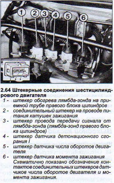
19. Six-cylinder engine. Disconnect the power supply plug to the ignition coils on the rear bulkhead of the engine compartment. The plug is painted white. Connect a voltmeter in turn to each of the three terminals at the top of the plug and to ground.
20. Turn on the ignition. The voltmeter should show at least 11.5 V. If there is no voltage at all or it is less than specified, then there is a defect in the wire to the ignition switch.
21. Perform the same measurement on the power supply wire of the ignition and fuel injection system control unit MPI/MPFI. The wire has black and green insulation. In this case, the voltmeter should show at least 11.5 V.
The ignition system failure in such cases may be caused by a faulty ignition switch or a broken power supply wire in the ignition switch/central switch panel and central switch panel/ignition coils or central switch panel/control unit circuit. Check the connecting wires using the electrical diagrams.
Ignition coil
Four and five cylinder engines
A visual inspection of the ignition coil condition was performed earlier. To check the ignition coil resistance, disconnect all wires from the coil, having turned off the ignition beforehand.
22. Measure the resistance of the primary and secondary windings of the coil using a highly sensitive ohmmeter.
23. Connect the ohmmeter to the coil terminals 1/- and 15/+. Nominal resistance value: 0.5-1.5 Ohm (see illustration).
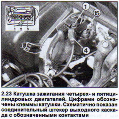
24. Perform the following measurement by connecting the ohmmeter to terminals 1/- and 4. In this case, the ohmmeter should show 5-9 kOhm. If the specified coil resistance values are not achieved, the coil should be replaced.
When performing the above measurements, it is impossible to determine whether there is a short circuit on the windings. If, despite good measurement results, there is still a suspicion that the coil is faulty, contact the appropriate workshop for a final check of the ignition coil.
Output stage
Four and five cylinder engines
The output stage cannot be tested in one go. It is tested in the following sequence:
25. Disconnect the output stage plug located next to the ignition coil.
26. Connect the voltmeter to the plug contacts 2 and 3 (ground),
27. Start the engine using the starter. The voltmeter should show at least 2 V.
28. Check the ignition system power supply as described above.
29. Check the ignition coil (see above).
If the system does not produce an ignition spark, despite the fact that all three mentioned tests have given a positive result, then the output stage is faulty.
30. Replace the output stage and ignition coil.
High voltage transformer
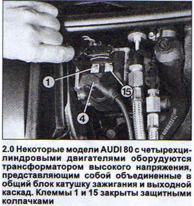
Some AUDI 80 models with four-cylinder engines have a common ignition coil and output stage unit. This unit is called a high-voltage transformer. The connecting terminals 1 and 15 of the ignition coil are in this case covered with protective caps. The ground connection passes through the housing (see illustration 2.0).
31. Disconnect the three-pin plug and the transformer main wire, after turning off the ignition.
32. Measure the resistance of the primary and secondary windings of the coil using a highly sensitive ohmmeter.
33. Connect an ohmmeter to coil terminals 1/- and 15/+. Nominal resistance value: 0.5-0.7 Ohm.
34. Perform the following measurement by connecting the ohmmeter to terminals 15 and 4. In this case, the ohmmeter should show 3-4 kOhm. If the specified resistance values are not achieved, the transformer should be replaced.
When performing the above measurements, it is impossible to determine the presence of a short circuit on the windings. If, despite good measurement results, there is still a suspicion that the coil is faulty, contact the appropriate workshop for a final check of the transformer.
To check the power supply, you need a voltmeter and auxiliary wires with tips.
35. Connect a voltmeter to both outer contacts of the three-pin plug and turn on the ignition. The voltmeter should show a voltage of about 12 V. If the voltmeter does not register voltage, then you need to check the power wire and the ground wire. One of them is broken.
36. Turn off the ignition.
37. Perform a pulse test. Disconnect the injector or fuel start valve plug and the injector power supply wire plug.
38. Connect the tester with the control diode lamp to contacts 2 and 3 of the transformer plug using auxiliary wires.
39. Ask an assistant to start the starter. The tester's LED should blink. If this does not happen, the Hall sensor or the fuel injection and ignition system control unit is faulty.
40. Turn off the ignition.
Ignition coil
Six-cylinder engines
41. Disconnect all high tension wires from the ignition coils.
42. Check the resistance of the secondary winding of the coil. To do this, connect a high-precision ohmmeter to the connectors of cylinders 1 and 6 (coil 1). The nominal resistance value is 9-14 kOhm.
43. In the same way, measure the resistance of the secondary windings of coils 2 and 3 by connecting the ohmmeter to the connectors of cylinders 2 and 4, 3 and 5, respectively.
If the obtained data corresponds to the nominal values, then check the resistance of the secondary winding of all coils.
44. Disconnect the white plug on the engine compartment bulkhead (ignition coil power plug).
45. Connect an ohmmeter to one of the three terminals 15 at the top of the plug.
46. Disconnect the three-pin plug of the output stage (also on the rear bulkhead of the engine compartment).
47. Connect the second wire of the ohmmeter to all three terminals of the plug one by one. The nominal value of all three measurements is 0.5-1.0 Ohm. If the values obtained during measurement do not correspond to the nominal ones, then replace the ignition coil pack.
Output stage
Six-cylinder engines
48. Disconnect the power plugs of all six injectors.
49. Disconnect the four-pin plug of the output stage (on the engine compartment bulkhead). If a three-pin plug is installed, the pin assignment is the same as for 4- and 5-cylinder engines (see illustration 2.23).
50. Connect the tester with the control diode lamp to the ground.
51. Connect the second tester lead alternately to contacts 1, 3 and 4 of the plug (see illustration).
Ask an assistant to turn the engine with the starter during each measurement. The control LED should blink during all three measurements. Otherwise, check the power supply or replace the output stage.
Hall sensor - check
Four and five cylinder engines
52. Disconnect the output stage plug.
53. Move the rubber cuff on the Hall sensor plug, thus providing access to the plug contacts from the back. Do not disconnect the Hall sensor plug itself. The plug is located on the side of the ignition distributor.
54. Connect the voltmeter to terminal 2 (wire with purple insulation) and terminal 3 (wire with purple-brown insulation) connecting plug.
55. Turn on the ignition and turn the engine by hand to engage the distributor.
The voltmeter should show a voltage of 0-0.5 V when the distributor diaphragm is outside the Hall sensor. When the diaphragm is under the Hall sensor, the voltmeter should show at least 4 V.
If the voltmeter does not register any pulses, then check the power supply to the Hall sensor.
56. Disconnect the distributor plug and connect a voltmeter to both outer contacts of the plug.
57. Turn on the ignition. The voltmeter should show at least 9 V. If not, the control unit is faulty or the Hall sensor power supply wire is broken.
Six-cylinder engines
58. Disconnect all injector plugs.
59. Move the rubber cuff on the Hall sensor plug, thus providing access to the plug contacts from the back side. Do not disconnect the Hall sensor plug itself.
60. Connect the tester with the control diode lamp to terminals 1 and 3 of the plug (the plug terminals are marked) and make sure that when the ignition is turned on, power is supplied to the plug. Otherwise, check the power wire.
61. Connect the tester with the control LED lamp to terminals 2 and 3.
62. Ask an assistant to turn the engine over with the starter. The LED light should blink. This means that the Hall sensor is normal.
Attention! If the Hall sensor is faulty, then the ignition distributor does not need to be changed. The Hall sensor is replaced separately.
Engine speed sensor
Six-cylinder engines
The engine speed sensor is located above the flywheel ring gear. The sensor's power supply wire is routed to the rear bulkhead of the engine compartment and secured at the top of the bulkhead. Therefore, there is no need to check the engine speed sensor from underneath the vehicle.
63. Check the power wire from the sensor to the holder on the rear bulkhead, as well as the plug connections.
64. Measure the sensor resistance using a high-precision ohmmeter. To do this, disconnect the three-pin plug and connect the ohmmeter to contacts 1 and 2 of the sensor power supply (see illustration).
The ohmmeter should show 1 kOhm. Otherwise, the sensor is faulty.
The third contact of the plug is connected to the shielding braid of the wire. To check the shielding braid, connect an ohmmeter to contacts 1 and 3, and then to 2 and 3. The ohmmeter should register infinite resistance. Otherwise, the engine speed sensor is faulty.
Attention! The next check of the sensor is its removal and cleaning of its end. A dirty end part of the sensor or grease that gets here disrupts the functioning of the sensor.
Caution! Do not disconnect the sensor holder. Only the sensor itself needs to be removed for inspection and cleaning. If the sensor holder has been disconnected, it must be installed in place by a workshop using special tools.
Ignition Timing Sensor - Check
Six-cylinder engines
The ignition timing sensor is mounted directly on the cylinder block. It is tested via a gray three-pin connector on the wire holder on the rear bulkhead of the engine compartment.
The procedure for checking the ignition timing sensor is identical to checking the engine speed sensor.
The injection and ignition system control unit in the usual sense of the word cannot be checked. The unit's malfunction can be established by interrogating the data storage device of the malfunctions that have occurred, by contacting the workshop to print out such information.