
Repair Chevrolet Repair Toyota Repair Honda Repair AvtoVAZ Repair Mercedes-Benz Repair BMW Repair Opel
Home  |  Contacts  |  Sitemap  |    
English Русский
Български
Беларускі
Український
Српски
Hrvatski
Română
Polski
Slovenský
Magyar
AudiManual.ru


  • AUDI 80
  • AUDI 100
  • AUDI A3
  • AUDI A4
  • AUDI A6
  • AUDI A8
  • AUDI Q
  • OTHER
  • ARTICLES
B4 (1991-1996) B3 (1986-1991) B3 (1986-1991, petrol) B2 (1979-1986)

General description and precautions (Audi 80 B4)

  • Home
  • Audi 80
  • B4 (1991-1996)
  • Power unit
  • Ignition system
  • General description and precautions
            0
The ignition system ensures the timely formation of the spark discharge necessary for ignition of the air-fuel mixture. At an engine speed of 3000 rpm, each engine cylinder requires 25 spark discharges per second. For the formation of a spark, the voltage between the spark plug electrodes must be at least 30,000 V. The battery voltage, which is 12 V, must be converted to the specified value and this conversion must be instantaneous. A delay of milliseconds leads to a decrease in the effective power of the engine.

The ideal moment for ignition of the air-fuel mixture is when the piston of the cylinder has reached TDC, providing maximum compression of the mixture, and is ready to move back. The gases formed during combustion of the mixture would provide the piston with a return force, which the piston would transmit to the engine. However, it would be a mistake to ignite the mixture when the piston of the cylinder is at TDC. A certain time is required for ignition of the air-fuel mixture and creation of the corresponding pressure in the cylinder (approximately 1/3000 sec). For this reason, ignition must occur early, at the moment the piston approaches TDC, so that the resulting pressure acts on the piston immediately after it leaves TDC. As the engine speed increases, the ignition advance angle must become increasingly early so that the ignition of the air-fuel mixture occurs at the same time (see illustration 1.0).
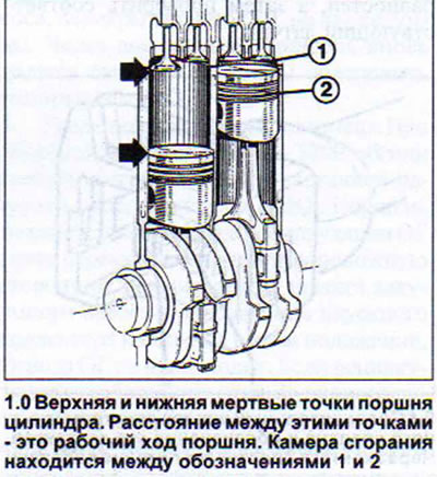
The ideal moment for ignition of the air-fuel mixture is when the piston of the cylinder has…


In addition, the ignition and combustion speed of the air-fuel mixture depends on its composition. For example, when the accelerator pedal is pressed lightly, the mixture in the combustion chamber is more difficult to ignite and burns more slowly. For this reason, the ignition moment must be earlier.


In some situations, late ignition is necessary when the ignition moment of the mixture must be shifted to a later time, when the cylinder piston has already passed TDC, for example, when descending in forced idle mode, when the engine is running without load (see illustration 1.0a).
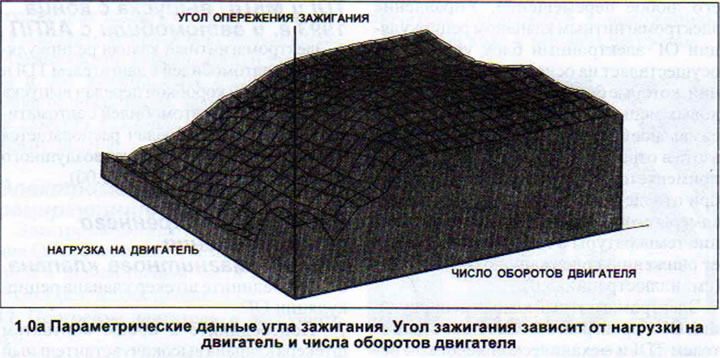
In some situations, late ignition is necessary when the ignition moment of the mixture must be…


Ignition control in vehicles with four and six-cylinder engines is performed by the fuel injection control unit. For this reason, the fuel injection and ignition systems have the same designation. Vehicles with a five-cylinder engine have a fully electronic ignition system (VEZ) and a separate ignition control unit that functions in close connection with the fuel injection control unit (see illustration 1.0b).
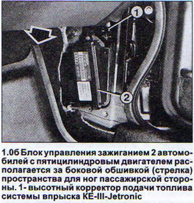
Ignition control in vehicles with four and six-cylinder engines is performed by the fuel injection…


Models with a four-cylinder 66 kW engine have a Mono-Motronic ignition system with automatic ignition timing.


The 85 kW four-cylinder engines are equipped with a Digifant ignition system with automatic ignition timing control.

Models with a six-cylinder engine are equipped with an MPI or MPFI ignition system that operates without a distributor. Each two cylinders of a six-cylinder engine, located opposite each other, have a common ignition coil that produces an ignition spark only when it is needed by the corresponding cylinder. Another, unused, but also harmless to the engine, spark is produced during the exhaust stroke.

The ignition system consists of:
  • a) spark plugs;
  • b) ignition coils with output stage;
  • c) ignition and fuel injection system control unit (excluding vehicles with five-cylinder engines);
  • d) sensors that supply various information to the control unit.

The supply and disconnection of power to the ignition coil is provided by the Hall sensor, which in cars with four- and five-cylinder engines is located in the ignition distributor, and in cars with six-cylinder engines - on the rear of the left cylinder head (see illustrations 1.0b and 1.0g).
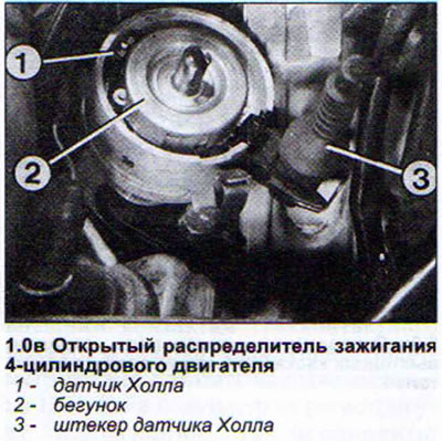
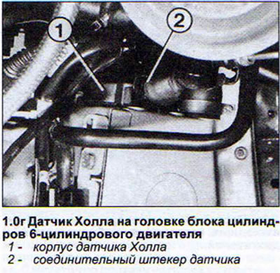
The supply and disconnection of power to the ignition coil is provided by the Hall sensor, which in…


The supply and disconnection of power to the ignition coil is provided by the Hall sensor, which in…


In addition to the Hall sensor, cars with a six-cylinder engine have an engine speed sensor and an ignition timing sensor. Both are inductive type sensors.


With the exception of 66 kW engines, all others have detonation combustion sensors. With the help of these sensors, the ignition advance angle is adjusted in such a way as to prevent detonation of fuel combustion (see illustrations 1.0d and 1.0g).
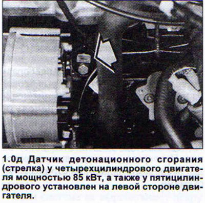
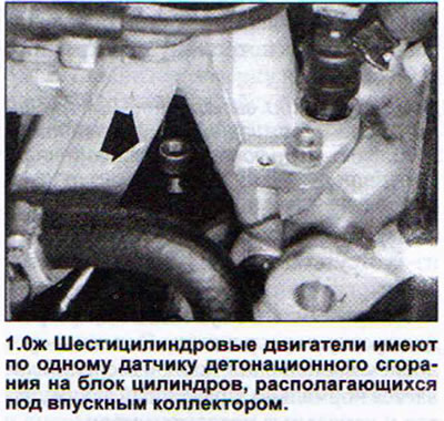
With the exception of 66 kW engines, all others have detonation combustion sensors. With the help…


With the exception of 66 kW engines, all others have detonation combustion sensors. With the help…


Attention! The knock sensor mounting bolt must be tightened with great precision, observing a tightening torque of 20 Nm. Otherwise, the sensor will not work.


To avoid electric shock, as well as failure of the ignition system as a whole or its components, it is necessary to observe the following safety measures. This especially applies to people with a pacemaker.
  • do not touch any wires, including those on measuring devices, until the ignition is turned off;
  • disconnect the battery terminals only after the ignition is turned off;
  • turn off the ignition before washing the engine;
  • do not leave the fast charger connected when forcibly starting the engine from it with a discharged battery for more than one minute. The voltage should not exceed 16.5 V;
  • disconnect the ignition system power plug if it fails and if it is necessary to tow the car to a workshop;
  • do not connect to terminal 1/- of the ignition coil capacitors;
  • replace a faulty distributor rotor only with a new one of the appropriate type. The rotor of 4- and 5-cylinder engines has a resistance of 1 kOhm and is marked R1;
  • connect only 1 kOhm resistors to thick high voltage wires of 4 and 5 cylinder engines;
  • use spark plug caps with 5k ohm resistance;
  • disconnect the battery when performing welding work on the vehicle.

Warning! The control unit or the ignition system output stage is damaged if you try to turn the engine over with the starter while the high-voltage wire is disconnected. To avoid this, it is recommended to disconnect the output stage plug for 4- and 5-cylinder engines (next to the ignition coil), and for 6-cylinder engines - both output stage plugs (on the rear bulkhead of the engine compartment) with ignition off (see illustration 1.0z and 1.0k).
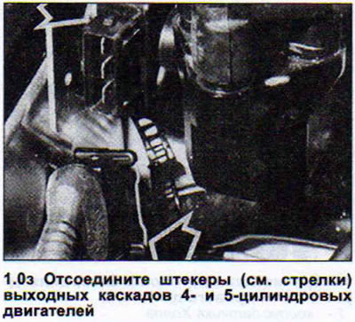
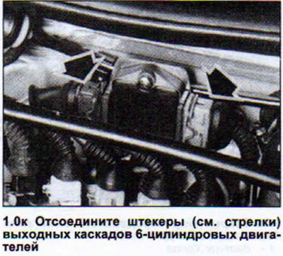


Warning! The control unit or the ignition system output stage is damaged if you try to turn the…


Warning! The control unit or the ignition system output stage is damaged if you try to turn the…


(This publication is borrowed from the resource AudiManual)
The article was checked by auto expert Timur Bazhenov
This article is available at russian, bulgarian, belarusian, ukrainian, serbian, croatian, romanian, polish, slovak, hungarian

Share information:
Previous articles
Audi 80 B4: Ignition system
Next articles

Ignition System Specifications
Ignition System — Troubleshooting
Ignition distributor — checking, removal and installation
High voltage wires
Spark plugs


Similar articles on other Audi car models:
General description and precautions Audi 100 C3 (1982-1990, diesel)
Generator — General Information and Safety Precautions Audi A3 Type 8L (1996-2003)
General information and safety precautions Audi A4 B6 (2000-2006)
General description and precautions Audi A6 C5 Allroad (1999-2005)
General information about the 2.8L petrol engine Audi A8 D2 (1994-2002)
General information and safety precautions: power supply system Audi Q7 Typ 4L (2005-2015, diesel)
Safety precautions when working with the fuel supply system Audi A2 (1999-2005)
Link to this page in different formats


Visitor comments

No comments yet


How much will 37 + 43 =


80(B4, 1991-1996) 
  • General information
  • User manual
  • Maintenance
  • Troubleshooting
  • Power unit
  • Engine
  • Cooling system
  • Heating and ventilation
  • Petrol injection
  • Diesel fuel system
  • Fuel system
  • Exhaust systems
  • Ignition system
  • Transmission
  • Clutch
  • Car gearbox
  • Chassis
  • Brake system
  • Suspension and steering wheel
  • Body
  • Body and trim
  • Electrical equipment
  • Electrical system
  • Electrical circuits
 
80(B3, 1986-1991) 
  • General information
  • Repair characteristics
  • Maintenance
  • Power unit
  • Gasoline engine
  • Diesel engine
  • Engine lubrication system
  • Fuel system (gasoline)
  • Injection system (gasoline)
  • Fuel system (diesel)
  • Ignition system
  • Cooling system
  • Heater
  • Exhaust system
  • Transmission
  • Clutch and gearbox
  • Chassis
  • Steering
  • Brake system
  • Car suspension
  • Body
  • Body elements
  • Electrical equipment
  • Power devices
  • Lighting and appliances
  • Electrical circuits
 
80(B3, 1986-1991, petrol) 
  • General information
  • User manual
  • Maintenance
  • Power unit
  • Engine 4-cylinder
  • Engine 5-cylinder
  • Cooling system
  • Fuel and exhaust systems
  • Ignition system
  • Transmission
  • Clutch
  • Mechanical transmission
  • Automatic transmission
  • Drive shafts
  • Chassis
  • Brake system
  • Suspension
  • Steering
  • Body
  • Exterior
  • Interior
  • Electrical equipment
  • Equipment and devices
  • Electrical circuits
 
80(B2, 1979-1986) 
  • General information
  • User manual
  • Power unit
  • Engine FZ
  • Engine EP, YP, YZ, DT, DS, DZ
  • Transmission
  • Clutch
  • 4 speed gearbox
  • 5 speed gearbox
  • Front wheel drive
  • Chassis
  • Front suspension
  • Rear suspension
  • Steering
  • Brake system
  • Electrical equipment
  • Equipment and devices
  • Electrical circuits
 
AudiManual.ru © 2017-2026 · Mobile version · Feedback · Sitemap: EN BG BY UA RS HR RO PL SK HU · Site search · News and articles
80 B2 · 80 B3 petrol · 80 B3 · 80 B4 · 100 C3 diesel · 100 C3 petrol · 100 C3 · 100 C4 petrol · 100 C4 · A3 Type 8L · A4 B5 petrol · A4 B5 · A4 B6 petrol · A4 B6 · A4 B7 · A4 B8 · A6 C4 · A6 C5 · A6 C5 Allroad · A8 D2 · Q5 Type 8R · Q7 Typ 4L · Audi A2 ·
This site uses cookies 🍪. Click the button to accept this fact.