Table of contents: Disconnecting the cylinder head cover ↓ Tightening sequence of cylinder head… ↓ Take off ↓ Install ↓ Cylinder head. ↓ Disconnecting the cylinder head ↓ Cylinder head bolt tightening… ↓ Removal the cylinder head ↓ Install ↓
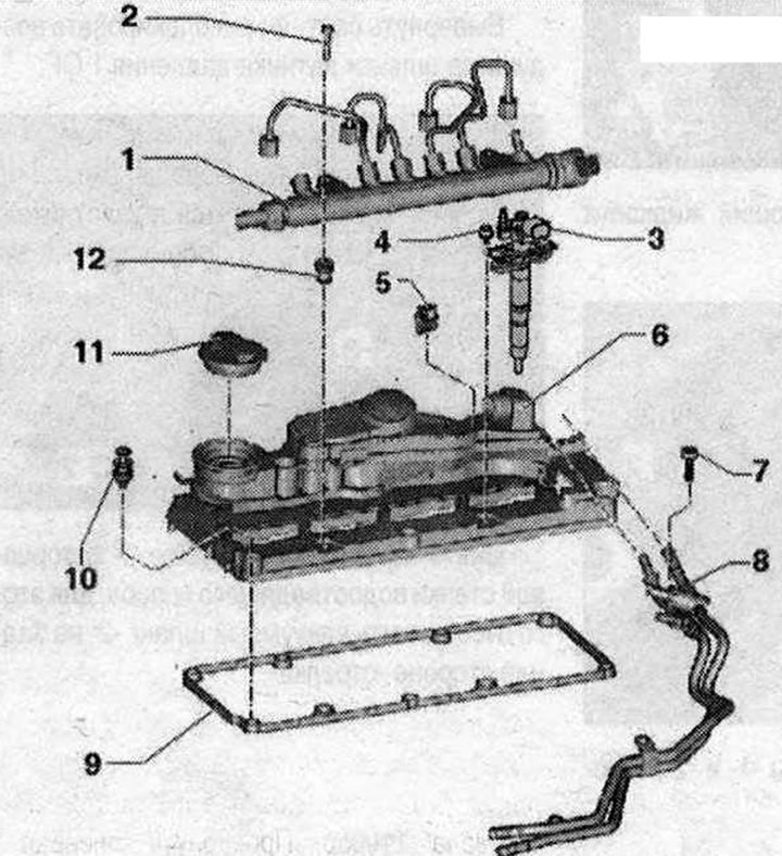
Cylinder head cover 1. Fuel rail, with fuel injection system pipes, do not change the curved shape of the fuel injection system pipes; 2. Bolt, 22 Nm; 3. Injection unit (piezo injector); 4. Bolt; 5. Latches; 6. Cylinder head cover; 7. Bolt, 10 Nm; 8. Fuel lines; 9. Gasket, replacement if damaged or leaking; 10. Bolt; 11. Lid; 12. Bushing, fuel rail fastening, replace if damaged
Disconnecting the cylinder head cover
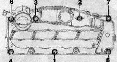
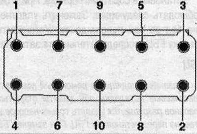
- 1. Loosen the nuts in the sequence "7...1".
Tightening sequence of cylinder head cover bolts
- 2. Tighten the bolts by hand in several stages in the sequence "1...7".
- 3. Tighten the bolts in the sequence "1...7" with a torque wrench to 10 Nm. Make sure that there are no distortions in the position of the cylinder head cover.
Take off
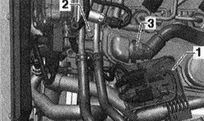
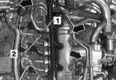
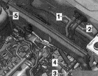
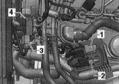
Remove the engine casing "arrows". Remove the noise-insulating injector pad. Remove the injectors. Remove the fuel rail. Unclamp the "arrows" clamps, remove the protective pad of the toothed belt. Remove bracket "1" with wiring for the lambda probe and temperature sensor in front of the diesel particulate filter from the cylinder head cover. Move and release the crankcase ventilation of the engine "3"
Loosen the bolts of the fuel lines "arrows".
Unscrew bolts "1...7" and remove the cylinder head cover.
Install
Installation in reverse order. Observe the following: Replace the bolt seal if damaged. Install the cylinder head cover, tightening sequence
Cylinder head.
Note: The plastic spacers included in the repair kit for protecting open valves may only be removed immediately before installing the cylinder head. When replacing the cylinder head, the coolant must also be changed.
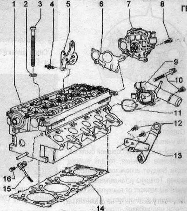
Cylinder head 1. Cylinder head, after replacement drain the old and fill the cooling system with new coolant; 2. Washer, for cylinder head bolt; 3. Cylinder head bolt, install washers in the cylinder head before installation; 4. Bolt, 25 Nm; 5. Hanging eye; 6. Gasket, replace; 7. Vacuum pump; 8. Bolt, 10 Nm; 9. Coolant connection nipple; 10. Bolt, 10 Nm; 11. Gasket, replace; 12. Bolt, 25 Nm; 13. Hanging eye; 14. Cylinder head gasket, replace, after replacement drain the old and fill the cooling system with new coolant; 15. Hall sensor "G40", for camshaft position, for removal and installation it is necessary to remove the toothed belt from the camshaft gears and unscrew the diverter roller; 16. Bolt, 10 Nm
Disconnecting the cylinder head
Loosen the cylinder head bolts in the following sequence:
Cylinder head bolt tightening sequence
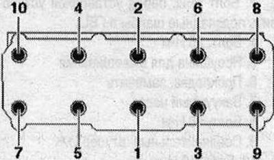
- 1. Tighten with a torque wrench to 40 Nm.
- 2. Tighten with a torque wrench to 60 Nm.
- 3. Tighten with a regular wrench by 90°.
- 4. Tighten with a regular wrench by 90°.
Tightening the cylinder head mounting bolts after repair work is not necessary.
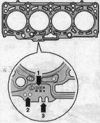
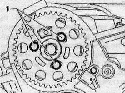
Cylinder head seal marking 1. Part number; 2. Holes; 3. Not taken into account
If different values were obtained for the piston protrusions, then the largest size should be used to select the gasket. The thickness of the installed seal. Cylinder head depends on the piston protrusion. When replacing, install a gasket with an identical marking "arrow 2".
Removal the cylinder head
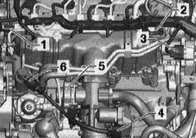
Disconnect the battery. Remove the tensioner. Drain the coolant. Remove the air filter housing. Remove the EGR radiator. Remove the inlet pipe. Remove the turbocharger. Remove the toothed belt. Remove the valve cover. Release the clamps of the "arrow" hose and remove the air duct hose.
Unscrew bolt "1".
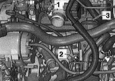
When working on the injection system, observe the rules for maintaining cleanliness. Disconnect the supply "1" and return "2" fuel lines.
Remove coolant hoses "3" and "4".
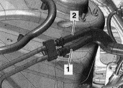
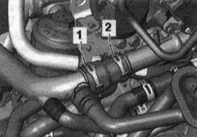
Remove hose clamps "1" and "2", disconnect the coolant hose.
Unscrew nut "3" of the EGR pipe. Unscrew bolts "4" and "5", move the EGR pipe to the side. The EGR pipe does not need to be removed.
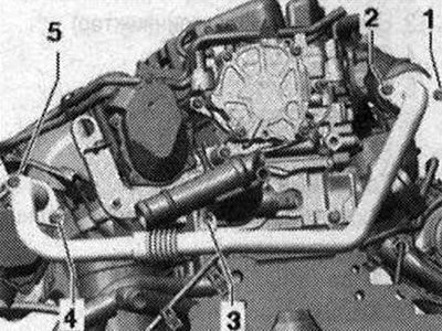
Unscrew the bolt "arrow" on the cylinder head of the pressure oil line going to the turbocharger.
Unscrew bolt "4", unlock the air hoses of the exhaust gas pressure sensor 1.
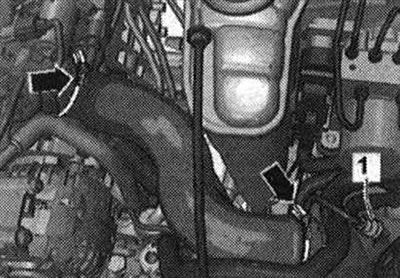
Remove the vacuum pipe "1" from the end wall of the water drain box, to do this, disconnect the vacuum hose "2" on the back side of the "arrow".
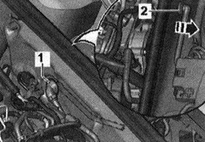
Disconnect the following plug connectors.
- 3. Variable geometry intake manifold servomotor "V183"
- 4. Intake manifold flap motor "V157"
- 5. EGR valve "N18"
Unscrew bolts "1" and remove the camshaft timing belt gear.
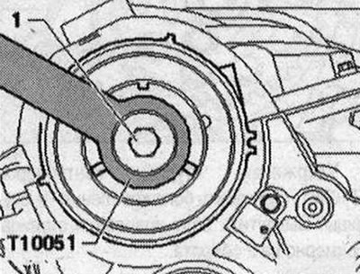
Unscrew bolt "1" of the camshaft hub, holding it with counter support "T10051". Unscrew the bolt by about 2 turns.
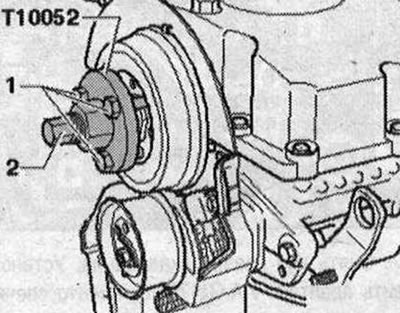
Place the puller "T10052" on the camshaft hub and screw bolts "1" into the hub. To remove the camshaft hub, screw bolt "2" and hold the puller by the hexagon (30). Remove the hub from the camshaft cone.
Remove bolt "1" of the belt protective cover.
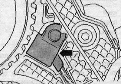
Unscrew the bolt of the Hall sensor "arrow", put the Hall sensor "G40" aside.
Loosen the cylinder head bolts in the sequence "1...10". A second mechanic is required to remove the cylinder head. Remove the toothed belt tension roller when removing the cylinder head from the mounting pin. First lift the cylinder head from the gearbox side and remove it from the toothed belt cover. Make sure that the toothed belt tension roller does not fall out.
Install
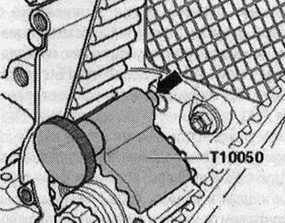
Install in reverse order. Observe the following: Risk of damaging the sealing surface. Carefully remove any sealant residue from the cylinder head and cylinder block. Avoid the formation of long scratches or scoring. Risk of damaging the cylinder block. There must be no oil or coolant in the blind holes of the cylinder head fastening bolts. Risk of cylinder head gasket leakage. During repairs, carefully remove any sealant residue from the cylinder head and cylinder block. Avoid the formation of long scratches or scoring. Carefully remove any residue after sanding and grinding. Remove the new cylinder head gasket from its packaging immediately before installation. Handle the gasket with particular care to prevent damage to the silicone layer and the grooves of the cylinder head gasket. Risk of damaging open valves. When installing an exchange cylinder head, remove the plastic base to protect the open valves only if it comes into direct contact with the cylinder head. Risk of damaging the valves and piston crowns after working on the valve mechanism. To ensure that no valve comes into contact with the cylinder head during operation, carefully rotate the crankshaft at least 2 turns. Replace the bolts tightened to the tightening angle. Replace the self-locking nuts, lip seals, gaskets and sealing rings. Modification of the cylinder head of TDI engines is prohibited. If a cylinder head from the exchange stock is installed, lubricate the contact surfaces between the rocker arm and the camshaft bearing housing. Hose nipples, air duct tubes and hoses must be cleaned of oil and grease before installation. To ensure reliable fastening of the air duct hoses on the nipples, treat the threaded connections of the already used clamps with a rust remover. After replacing the cylinder head or cylinder head gasket, completely replace the coolant and oil. Before installing the cylinder head, remove the crankshaft lock "T10050" and turn the crankshaft against the direction of rotation of the engine shaft until all pistons are evenly below TDC. For centering, screw the guide bolt "3070" into the outer holes on the intake side. Apply the cylinder head gasket with the marking facing up.
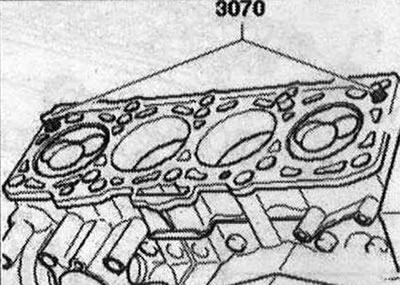
Pay attention to the marking of the cylinder head gasket: If different values were obtained for the piston protrusions, then the largest size should be used for selecting the gasket. The thickness of the cylinder head seal to be installed depends on the piston protrusion. When replacing, install a gasket with an identical marking "arrow 2". When installing the cylinder head, the tensioner roller must be installed on the stud. Put on the cylinder head, insert the remaining 8 cylinder head screws and tighten by hand. Using a screwdriver, unscrew the guide bolt from 3070 through the screw holes and install the cylinder head screws. Then tighten the cylinder head bolts in 4 stages. Fasten the rear toothed belt guard to the cylinder head. Install the hub and camshaft gear. Secure the camshaft and high-pressure pump with the locking pin for the unit injector "3359". Turn the crankshaft in the direction of engine rotation to TDC and secure with the crankshaft lock "T10050". Install the toothed belt. Installation in reverse order. In this case, it is necessary to consider the following: Install the cylinder head cover. Install the poly V-belt. Fill with coolant.