
Table of contents: Tightening sequence - 8-threaded… ↓ Tightening sequence - 6-point… ↓ Mounting position of thrust bearing… ↓
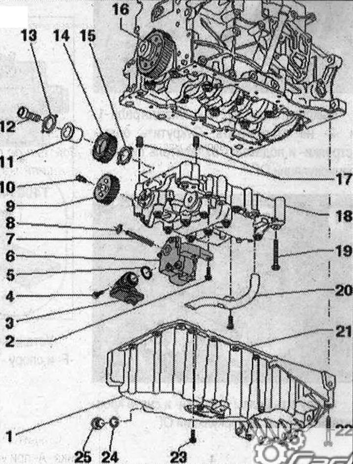
Oil pan, oil pump, balance shaft block. I 1. Oil pan; 2. Bolt, 10 Nm; 3. Suction pipe, if dirty, clean the mesh filter; 4. Bolt, 10 Nm; 5. Sealing ring, replace; 6. Oil pump, before installation, check whether both installation bushings for centering the oil pump on the balance shaft module are in place; 7. Oil pump drive shaft; 8. The retaining ring must fit into the groove base; a damaged or overtightened retaining ring must be replaced; 9. Balance shaft gear; 10. Bolt, 20 Nm + 90°, replace; 11. Hub, intermediate gear, replace; 12. Bolt, 90 Nm + 90°, replace; 13. Thrust bearing washer, intermediate gear, replace; 14. Intermediate gear, replace, to achieve the required tooth profile clearance, a coating is applied to the new intermediate gear, which ensures the correct clearance due to wear. When installing the intermediate gear, pay attention to the correct fit of the thrust bearing washer, installation position: the part number must be visible; 15. Replace the thrust bearing washer, intermediate gear. Take into account the mounting position, if necessary, fix it to the housing with grease for mounting the intermediate gear; 16. Cylindrical gear wheel; 17. Guide bushings, centering bushings of the balance shaft module on the cylinder block; 18. Balance shaft module, before installation, check that both installation bushings for centering the balance shaft module on the cylinder block are in place; 19. Bolt, replace; 20. Oil intake pipe; 21. Bolt, 10 Nm; 22. Bolt, 40 Nm; 23. Bolt, 15 Nm, tighten in stages in a crisscross pattern; 24. Lip seal, replace; 25. Oil drain plug, 30 Nm
Tightening sequence - 8-threaded balance shaft module
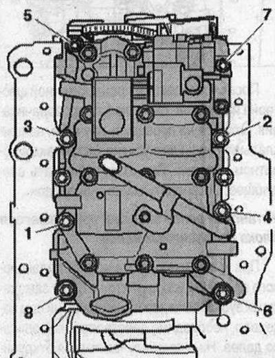
Tighten the balance shaft module bolts in the following order:
| Step | Bolts | Tightening torque/angle of rotation |
| 1. | "1...8" | tighten by hand in sequence |
| 2. | "1...8" | pre-tighten in the specified sequence to 6 Nm |
| 3- | "1...4" | tighten to 20 Nm |
| 4. | "5" | tighten to 13 Nm |
| 5. | "6" | tighten to 20 Nm |
| 6. | "7" | tighten to 13 Nm |
| 7. | "8" | tighten to 20 Nm |
| 8. | "1...8" | tighten with a rigid wrench by 90° in sequence |
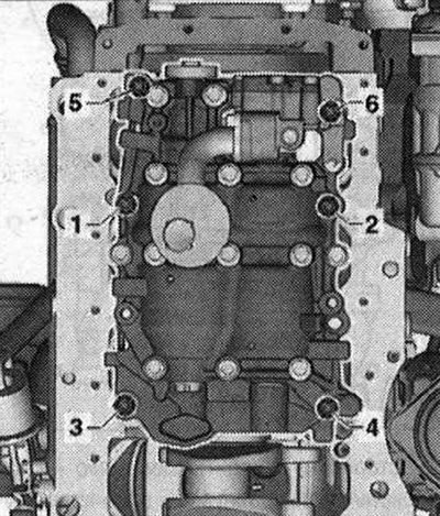
Tightening sequence - 6-point balance shaft module
Tighten the balance shaft module bolts in the following order:
| Step | Bolts | Tightening torque/angle of rotation |
| 1 | "1...6" | tighten by hand in sequence |
| 2 | "1...6" | Pre-tighten the bolts in sequence to 6 Nm |
| 3 | "1...4" | tighten to 20 Nm |
| 4 | "5 and 6" | tighten to 13 Nm |
| 5 | "1...6" | tighten with a rigid wrench by 90° in sequence |
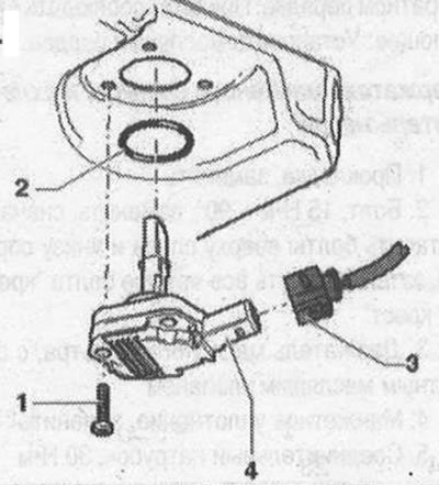
Oil level and temperature sensor "G266". I 1. Bolt, 15 Nm; 2. Sealing ring; replacement; 3. Electrical plug connection; 4. Oil level and temperature sensor "G266"
Mounting position of thrust bearing washer
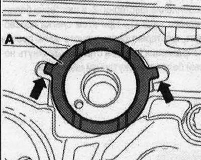
Make sure that the thrust bearing washer "A" does not slip out of the recesses of the balance shaft module "arrow" when installing the intermediate gear and does not become jammed as a result. If necessary, fix it with grease on the balance shaft module.