
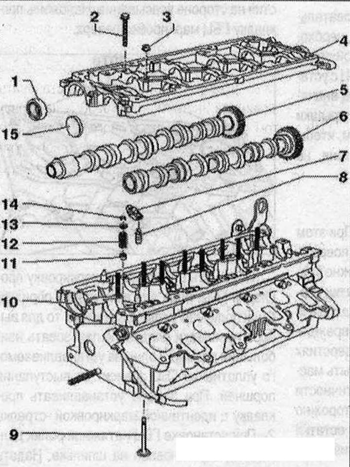
Valve mechanism 1. Seal shaft ring; 2. Bolt; 3. Nut; 4. Support frame, with built-in camshaft liners; 5. Exhaust camshaft; 6. Intake camshaft; 7. Rocker arm, mark mounting position for reinstallation. Check the roller bearing for ease of movement, lubricate the working surfaces before installation; 8. Hydraulic compensator, with locking bracket, mark the installation position for re-installation, lubricate the working surfaces before installation; 9. The valve cannot be processed, only grinding is allowed, mark the mounting position for re-installation; 10. Cylinder head; 11. Valve seal; 12. Valve spring; 13. Valve spring retainer; 14. Valve retainer; 15. Cover, replace, removal: with the camshaft frame removed, pierce the cover on one side with an awl and remove it, installation: press in with a suitable mandrel without sealant, press-in depth 1-2 mm
Support frame - bolt sequence and torque
Tighten the bearing frame bolts and nuts in sequence -1...24- in 2 steps, as follows:
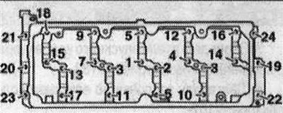
- 1. Screw in evenly by hand until it stops. The frame must be in contact with the cylinder head over the entire contact surface.
- 2. Tighten to 10 Nm.
Removing camshafts
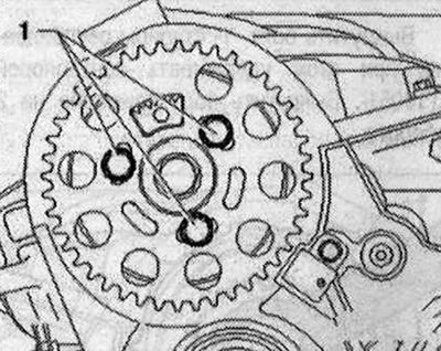
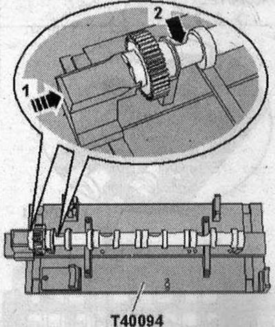
Remove engine cover -arrows-. Remove the noise insulation pad for the injectors. Remove the injectors. Remove fuel ramp. Remove the camshaft and high-pressure pump timing belt. Remove the valve cover. Unscrew the mounting bolts -1-camshaft gear. Remove the camshaft from the hub.
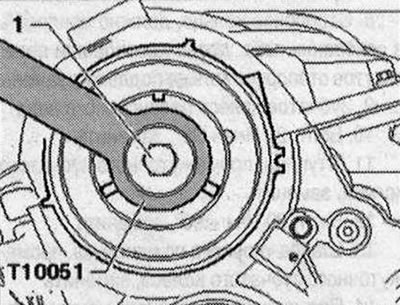
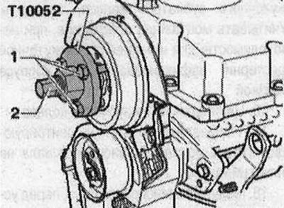
Hold the hub with a counter support -T10051 - and loosen the hub mounting bolt -1 -. Unscrew the hub mounting bolt approximately 2 turns.
Install puller -T10052- and align with hub holes. Tighten the mounting bolts -1. Increase the tension on the hub by evenly tightening the puller -2- until the hub is released from the camshaft cone. At the same time, secure the puller using a 30mm wrench. Remove the hub from the camshaft cone. Remove the vacuum pump.
Remove vacuum hose -1-.
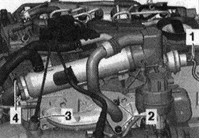
Remove bolts -2- and -4-. Do not unscrew lines -1- and -2-. Unscrew bolts arrows and attach exhaust gas recirculation cooler.
Unscrew the bolts -arrows- and remove the bracket for the exhaust gas recirculation system.
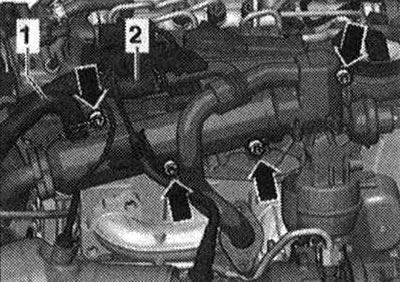
Unscrew the frame mounting bolts in the sequence -24...1-. Remove the camshaft frame. Mark for reinstallation and remove the camshafts.
Install
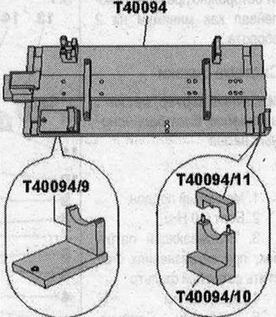
Apply silicone adhesive sealant to the seating surfaces between the crankshaft frame and the cylinder head. The camshafts must only be installed using the camshaft stand -T40094- as described below. Remove any remaining sealant on the cylinder head and camshaft frame, for example using a rotating brush with plastic bristles. Cover exposed parts of the engine. Remove any remaining sealant from the cylinder head and crankshaft frame, for example, using a rotating brush with plastic bristles. Clean the seating surfaces; There should be no oil or grease on them. Lubricate the working surface of the camshafts with oil. Equip the camshaft installation tool -T40094- as follows: Screw on the supports -T40094/9- and -T40094/10- (s -T40094/11 -) onto the main plate as shown in the picture. If necessary, unscrew the screwed supports at this location.
Place support -T40094/1 - at position -F- and support -T40094/2- at position -A-.
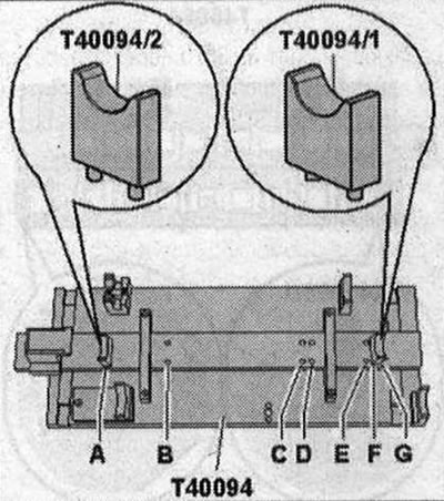
Place intake camshaft on supports -T40094/1- and -T40094/2-. Rotate the intake camshaft until it can be locked in position "TDC" -arrow 1-. The concavity -arrow of the 2nd cylinder head bolt must face outwards.
Place exhaust camshaft on supports -T40094/9- and -T40094/11 -. Secure the exhaust camshaft with the cover -T40094/11 -. The protrusion -1- of the cover must fit into the groove -2- in the camshaft. Position the clamping tool -T40096/1- on the exhaust camshaft gearing so that each journal of the clamping device engages on each gear half. The wide journal should fit into the wide half of the gear. Tighten the clamping device using the knurled wheel until the tooth profiles are level. Push the intake camshaft towards the exhaust camshaft until their teeth engage -arrows-.
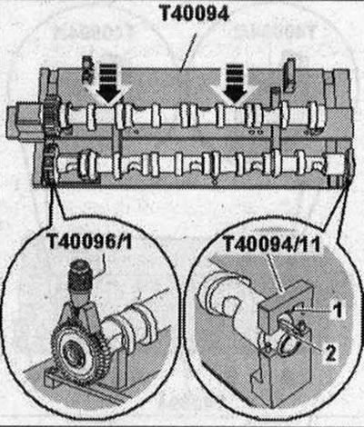
Install the frame onto the camshafts. All camshaft bearings must be on the camshafts. Install the camshaft stand -T40095- and secure the camshafts in the frame as shown in the illustration. Remove cover -T40094/11-.
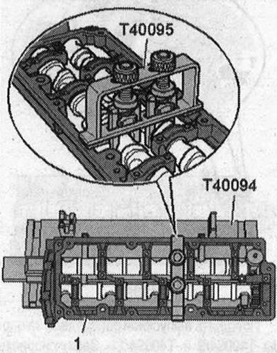
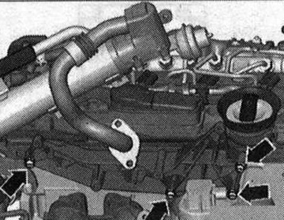
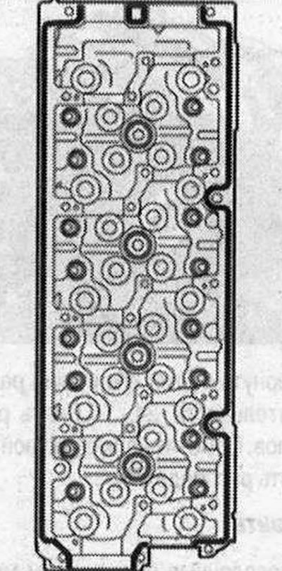
Cut off the tube spout at the front mark (hole about 2mm). Apply beads of sealant (width approx. 2...3 mm) -arrows- onto clean seating surfaces of the cylinder head, as shown in the figure. The sealant beads should not be thicker than specified, otherwise excess sealant may get into the camshaft bearings. Remove the camshafts together with the frame, camshaft stand -T40095- and clamping tool -T40096/1- from the camshaft stand -T40094- and carefully insert into the cylinder head.
Tighten the frame mounting bolts in the sequence -1...24- first by hand. The frame must be in contact with the cylinder head over the entire contact surface. Tighten the frame bolts in the sequence -1...24-. Remove camshaft installation tool -T40095- and clamping device -T40096/1-. Installation is carried out in reverse order, observing the following: Replace the camshaft seal. Press the new locking cover flush onto the cylinder head using a suitable mandrel. Install the vacuum pump. Install the cylinder head cover. Risk of damage to valves and piston crowns after working on the valve mechanism. Since the hydraulic lifters must be seated, after installing the camshafts, the engine should not be started for approx. 30 min. To ensure that no valve comes into contact with the cylinder head during operation, carefully turn the crankshaft at least 2 turns.
Visitor comments