
Table of contents: Balance shaft module with 8 threaded… ↓ Balance shaft module with 6 threaded… ↓ Installing a new balance shaft module ↓ Installation of a previously used… ↓
Release the clamps "arrows", remove the protective cover of the toothed belt. "Pos. 1" do not take into account. Risk of damage due to slipping of the toothed belt. Turn the crankshaft only in the direction of engine rotation. Turn the crankshaft by the toothed belt bolt so that the camshaft is at "TDC".
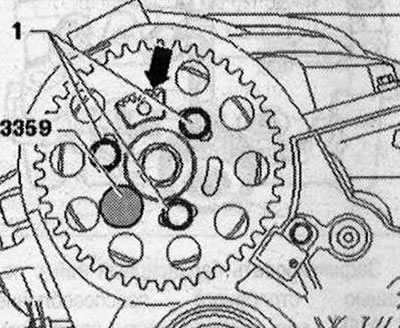
Secure the camshaft hub with the locking pin of the direct injection pump of the diesel engine "3359". The toothed segment "arrow" should be directed upwards. Remove the oil pan.
Balance shaft module with 8 threaded connections
Unscrew the bolts in the sequence "8...1" and remove the balance shaft module with the oil pump.
Balance shaft module with 6 threaded connections
Unscrew the bolts in the sequence "6...1" and remove the balance shaft module with the oil pump.
Installing a new balance shaft module
The gear drive engagement of the balance shaft unit must have the correct lateral clearance. To achieve the required tooth profile clearance, a coating is applied to the new intermediate gear. When first used, this coating wears off quickly, thereby ensuring the required lateral clearance. Therefore, when installing a new balance shaft unit, a new intermediate gear with the appropriate coating must always be installed. Replace the bolts tightened to the tightening angle. Risk of the thrust bearing washer slipping behind the intermediate gear. When installing the balance shaft module, do not loosen the intermediate gear bolt of the shaft more than specified. Mounting position of the thrust bearing washer. Loosen bolt "1" of the intermediate gear by approximately 45°. If the centering bushings of the balance shaft module are missing on the cylinder block, insert the bushings. Do not allow the coating of the intermediate gear to be damaged. Place the balance shaft module on the cylinder block. Tighten the 8-point balance shaft assembly. Tighten the 6-point balance shaft assembly.
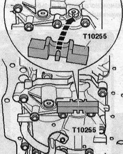
Fix the balance shaft using the locking device "T10255", if necessary, rotate the shaft. The journal of the locking device should enter the groove of the balance shaft.
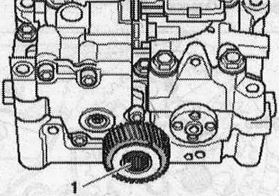
Carefully place the gear on the balance shaft, shifting the intermediate gear slightly to the side. In this case, the threaded holes of the balance shaft should be, if possible, exactly in the middle of the concentric grooves of the gear wheel. If the longitudinal holes in the balance shaft gear do not match the threaded holes, it is necessary to turn the gear by the corresponding number of teeth and put it on again. Screw on the balance shaft gear "arrow". Remove the locking device "T10255".
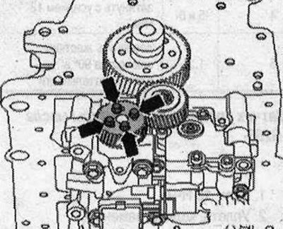
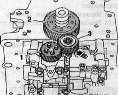
The following 3 stages of work must be completed simultaneously (assistance from a second mechanic is needed): Press the intermediate gear "3" with force, if necessary with a wooden block, "in the direction of the arrow" into the toothed engagement of gear "2" and balance shaft gear "1". At the same time, turn the balance shaft gear slightly counterclockwise. Tighten the new intermediate gear bolt.
After installation, there should be no play in the intermediate gear. This can be checked manually without applying much force. Installation is in reverse order. In this case, observe the following: Install the oil pan.
Installation of a previously used balance shaft unit
When installing the old balance shaft module, provided that neither the crankshaft gear nor the crankshaft itself have been replaced, it is necessary to act as described below. Under no circumstances should the intermediate gear be unscrewed. If the intermediate gear bolt has been unscrewed or loosened, or the crankshaft gear or the crankshaft itself has been replaced, it is necessary to install a new intermediate gear with a coating. Replace the balance shaft module bolts. Secure the balance shaft using the locking device "T10255"; if necessary, rotate the shaft. The journal of the locking device must enter the groove of the balance shaft. If the cylinder block does not have centering bushings for the balance shaft module, insert the bushings. Place the balance shaft module on the cylinder block. With the balance shaft locked, the intermediate gear must engage with the toothed wheel on the crankshaft. The intermediate gear must have a clearly visible play in rotation. Tighten the balance shaft module with 8 threaded connections. Tighten the balance shaft module with 6 threaded connections. Install in the reverse order. In this case, observe the following: Install the oil pan.
(The original text of the material can be found on the website: «AUDIMANUAL.RU»)