
Examination
Check the engine oil level and top it up if necessary.
Warm up the engine to normal operating temperature (80°C).
Disconnect the electrical connector from the oil pressure sensor.
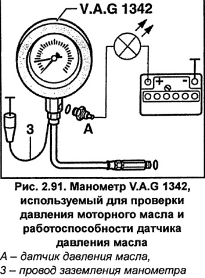
Unscrew the oil pressure sensor A (Fig. 2.91) from the oil filter holder and screw it into the pressure gauge. On V6 petrol engines, the oil pressure sensor is screwed into the oil pan.
Screw the pressure gauge adapter into the oil filter holder in place of the oil pressure sensor.
Connect wire 3 (Fig. 2.91) of the VAG 1342 pressure gauge ground to the vehicle ground.
Using additional wires, connect the indicator LED to the positive battery terminal and the oil pressure sensor contact.
Petrol engines:the LED should be on.
Diesel engines: the LED should not light.
Start the engine and gradually increase the engine speed.
Petrol engines: at a pressure of 1.2-1.6 bar the LED should light up.
Diesel engines:at a pressure of 0.75-1.05 bar the LED should go out.
Otherwise, the oil pressure sensor is faulty.
Increase the engine speed to 2,000 rpm. At an oil temperature of +80°C, the oil pressure should be at least 2.0 bar (for a 125 hp engine - 4.5 bar). For a 150 hp gasoline engine at 3,000 rpm, the oil pressure should be 3.0-5.0 bar.
Lower oil pressure indicates worn crankshaft bearings.
V6 Diesel Engine: with further increase in rotation speed, the oil pressure should not exceed 7.0 bar. Otherwise, the bypass valve is out of order and it is necessary to replace the oil pump cover.
Install the oil pressure sensor with a new sealing ring and tighten it to 25 Nm.
Connect the electrical connector to the oil pressure sensor.
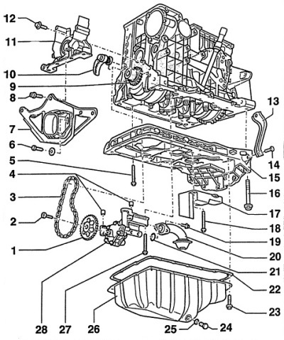
Fig. 2.92. Oil pump and oil pan of the 1.8-I/125 hp engine.
1 - asterisk,
To drive the oil pump.
2 - bolt, 10 Nm,
3 - oil pump drive chain,
Before removing, mark the direction of rotation of the chain.
4 - centering bushings,
Determine the relative position of the oil pump and the cylinder block.
5 - bolt, 15 Nm,
6 - bolt, 30 Nm,
7 - torque compensator support,
8 - bolt, 40 Nm,
9 - asterisk,
10 - chain tensioner,
It cannot be disassembled. If the spring breaks, it must be replaced.
11 - front cover,
When installing, it is necessary to apply sealant AUDI- D176404A2 to the mating surface.
12 - bolt, 15 Nm,
13 - support for the suction pipe,
14 - bolt, 20 Nm,
15 - frame,
When installing, it is necessary to apply sealant AUDI-D176404A2 to the mating surface.
When installing the frame, make sure that the frame protrudes towards the gearbox by 0.8 mm in relation to the cylinder block.
16 - bolt, 40 Nm,
17 - wave damper,
18 - bolt, 15 Nm,
19 - bolt, 10 Nm,
20 - oil receiver,
If dirty, clean the mesh filter.
21 - sealing ring,
22 - oil pan gasket, 23-bolt, 15 Nm,
Tighten the bolts crosswise in several stages.
24 - oil drain plug, 30 Nm,
25 - sealing ring,
A new sealing ring must be used during installation.
26 - oil pan,
27 - bolt, 15 Nm,
28 - oil pump.
Maximum pressure 12 bar.