
Table of contents: Removal ↓ Engines with two valves per cylinder… ↓ Engines with five valves per… ↓ Installation ↓ Engines with two valves per cylinder… ↓ Engines with five valves per… ↓ Features of the right cylinder head… ↓
Remove the cylinder head only when the engine is cold (at room temperature). Do not disconnect the exhaust pipe. The cylinder head can be removed without removing the engine. The description applies to the left cylinder head. The right cylinder head is removed in a similar manner.
Defects in the cylinder head gasket are determined by various signs.
Warning: Cylinder head bolts must be tightened very carefully. The torque wrench must be checked for accuracy before tightening. Cylinder head bolts must be tightened on a cold engine.
Removal
1. Unhook the water drain cover at the bottom of the engine compartment between the front wall and the windshield and remove it.
2. Disconnect the battery ground (–) cable.
Warning: Before disconnecting, please read the instructions in subsection 8.1.3.2.
Warning: In vehicles with air conditioning, the battery is located under the rear seat.
3. Remove the poly V-belt.
4. Raise the car.
5. Remove the lower engine compartment cover.
6. Loosen the toothed belt and remove it from the camshaft gears. Do not remove the torsional vibration damper.
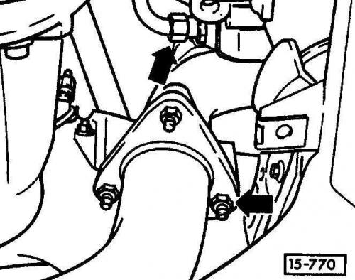
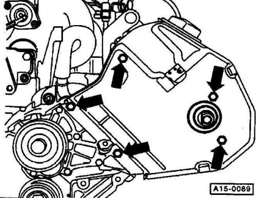
7. Unscrew the exhaust pipe from the exhaust outlet (the arrows show the location of the fastening elements).
8. Unscrew the gas line at the mechanical valve of the exhaust gas recirculation system (eGR valve). The connection point is located at the left pipe next to the oxygen sensor.
9. Drain the coolant.
10. Remove the air hose between the air flow meter and the intake manifold.
11. Unscrew the crankcase ventilation system on the left and right of the cylinder head.
12. Unscrew the fuel supply and outlet pipes to the left and right of the ring pipeline at the bottom of the intake manifold. Place a rag under the connection point, loosen the nuts slowly to relieve pressure. Plug the pipes with the appropriate plugs.
13. Loosen the muffler cover. To do this, insert a wrench between the intake manifold and the cover and slide it up.
14. Remove both bolts under the cover.
15. Press the muffler cover down, pull it towards the throttle body and pull it up.
16. Disconnect the following vacuum hoses. To facilitate assembly, label the hoses with tags beforehand.
- vacuum hose to the left of the muffler cover;
- hose of the left connecting pipe of the crankcase ventilation system.
17. Remove the noise muffler.
18. Label and remove the following vacuum lines.
- brake booster vacuum line on the right side of the intake manifold and at the vacuum pump on the right cylinder head;
- vacuum hose on top of the EGR box. The box with the mechanical bypass valve is located on the left at the bottom of the intake manifold;
- vacuum pipeline of the GRA system box (black plastic box). The GRA system switches the intake manifold valve, the box is located next to the EGR system box;
- vacuum line of the throttle valve activated carbon filter tact valve;
- vacuum lines at the intake manifold changeover valve (blue) and at the electric EGR valve (brown). Both valves are located under the air flow meter.
19. Using a SW 5 Allen key, unscrew the cover of the valve injector wires on the left.
20. Unclip the throttle linkage, remove and set aside.
21. Remove or disconnect the following wires. To facilitate reassembly, label the wires with tags.
- all spark plug plugs;
- all valve injector plugs;
- idle speed control valve plug on the bottom right side of the intake manifold;
- throttle position sensor plug at the bottom of the throttle valve pipe;
- oil pressure sensor and hydraulic switch plug at the bottom of the left cylinder head;
- oxygen sensor and heating system oxygen sensor plug from the end of the cylinder block, next to the left cylinder head.
Warning: Loosen the cable tie and cut it off if necessary. Do not remove the tie so that a new cable tie can be installed in the same place when reassembling the engine.
22. Remove the mechanical EGR valve from the intake manifold.
23. Unscrew the holder of the hydraulic line and ground wires at the intake manifold on the right.
Engines with two valves per cylinder (up to 174 hp)
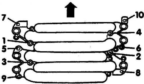
Cylinder head - 6-cylinder petrol engine (2 valves per cylinder, up to 174 hp)

- 1. Bolt, 20 Nm
- 2. Intake manifold
- 3. Bolt, 10 Nm
- 4. Lid
- 5. Bolt, 10 Nm
- 6. Cylinder head bolt
- 7. Oil pressure sensor, 25 Nm
- 8. Hydraulic switch, 25 Nm
- 9. Hollow bolt, 25 Nm
- 10. Bolt, 10 Nm
- 11. Hall sensor housing
- 12. Cylinder head
The left and right cylinder heads are interchangeable. Therefore, the head must be supplied with the appropriate cover before installation.
- 13. Cylinder head gasket
Execution order
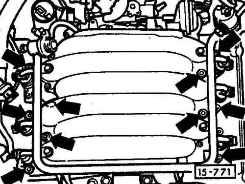
1. Unscrew and remove the intake manifold (the location of the fasteners is shown by arrows).
2. Cover the holes with one clean cloth to prevent dirt from getting inside.
3. Unscrew the coolant pipe at the bottom of the cylinder head.
4. Unscrew the CO sampling tube from the front outlet pipe and from the bracket.
5. Remove the oxygen sensor.
6. Remove the heat shield from the exhaust pipe.
7. Using a size 5 Allen key, unscrew the cylinder head cover and remove it together with the oil level indicator.
8. Remove the cylinder head cover gasket.
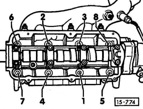
9. Loosen the cylinder head bolts in reverse order of their numbering, from 8 to 1, first by 1/2 turn, then unscrew.
Engines with five valves per cylinder (with a working volume of 2.8 liters (30 valves), 193 hp)
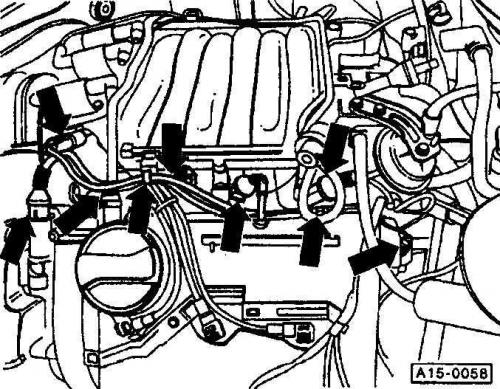
1. Remove the camshaft and valve injector adjustment plug (the location of the fastening elements is shown by arrows).
2. Cut the cable tie at the valve cover, loosen the cable clamp at the injection line, and remove the crankcase ventilation system from the cylinder head cover.
3. Remove the four fuel rail bolts at the intake manifold.
4. Disconnect the fuel supply and return lines from the holder.
5. Remove and set aside the fuel manifold with the valve injectors. Cover the valve injectors with a clean rag.
6. Unscrew the ignition coils together with the bracket (4 bolts).
7. Place a wooden block of approximately 90 mm height under the gas pedal. Unscrew the GRA box (speed controller), remove the ball joint from the throttle actuator.
8. Unscrew the intake manifold.
9. Unscrew the lower left timing belt cover.
10. Remove the two coolant pipe bolts from the cylinder head.
11. Check that all wires and hoses going to the cylinder head have been removed.
12. Loosen the cylinder head bolts in reverse order of their numbering, from 8 to 1, first by 1/2 turn, then unscrew.
13. Remove the cylinder head and place it on 2 wooden blocks.
14. Remove the cylinder head gasket.
Installation
1. Before installation, clean the cylinder head and cylinder block from seal residues using a suitable scraper. Make sure that dirt does not get into the cylinder block holes. Cover the holes with rags.
2. Check for oil in the cylinder head bolt holes, remove if there is. Check the cylinder head for deflection using a steel ruler. Check the deflection using a steel ruler and a feeler gauge in various places on the cylinder head. The maximum permissible unevenness should not exceed 0.1 mm.
Warning: If the contact surfaces of the cylinder head are pre-machined, the permissible height of the re-machined head must not be less than a certain minimum height. The minimum height of the re-machined cylinder head is 132.75 mm (for an engine with a working volume of 2.8 l and 30 valves - 139.25 mm).
3. Check if the cylinder head bolt holes are free of oil, remove the oil if necessary. If it is not possible to blow out the holes with compressed air, then you need to take a small screwdriver and a well-absorbent cloth and use them to clean the holes from oil.
4. The cylinder head gasket must be replaced. The inscription on the gasket must face the cylinder head. Place the gasket dry and on a dry surface so that the holes in the cylinder block are not covered.
5. Guide bushings are provided to center the sealing gasket and the cylinder head.
6. Reserve the correct locations for the guide bushings.
Warning: If a new cylinder head is installed, a plug must be installed at the front end beforehand. This is necessary so that the cylinder head installed as a spare part can be installed on either the right or left side.
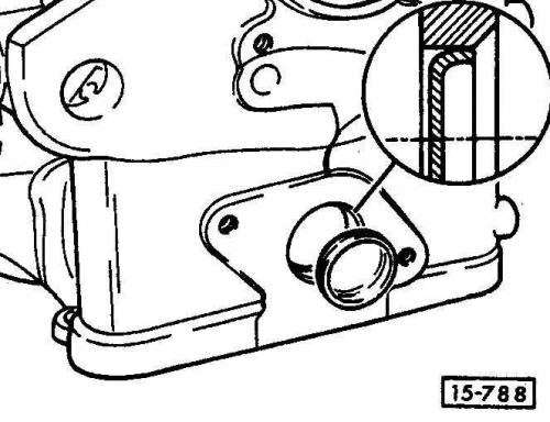
7. Lubricate the outer edge of the plug with AMV 1880002 sealant. Use the VW-295 rod to deepen the plug so that its outer edge is flush with the cylinder head mounting chamfer (the figure shows the location of the plug).
8. Carefully install the head using the hoist.
9. Insert the cylinder head bolts with washers and tighten them by hand. Be sure to replace the cylinder head bolts with new ones.
Engines with two valves per cylinder (up to 174 hp)
1. The cylinder head bolts are tightened in two stages. In each stage, tighten the bolts in sequence from 1 to 8.
Method 1: using a torque wrench with a torque of 60 Nm.
Method 2: without stopping tightening, turn in the tightening direction by 1/2 turn (180 degrees) using a locked key. It is permissible to perform this technique as 2 tightenings of 90 degrees.
2. When tightening the cylinder head bolts, evaluate the angle of rotation of the wrench. Place the handle of the wrench along the cylinder head and turn it in one stroke to a position perpendicular to the axis of the head (1/4 turn is 90 degrees). Then turn the key further until the key handle is again positioned along the cylinder head.
Warning: Subsequent tightening of the cylinder head bolts on a warm engine is not required and is not permitted. When installing a replacement cylinder head with the camshaft installed, lubricate the contact surfaces of the plate tappets and cams after installing the cylinder head.
3. Install the timing belt.
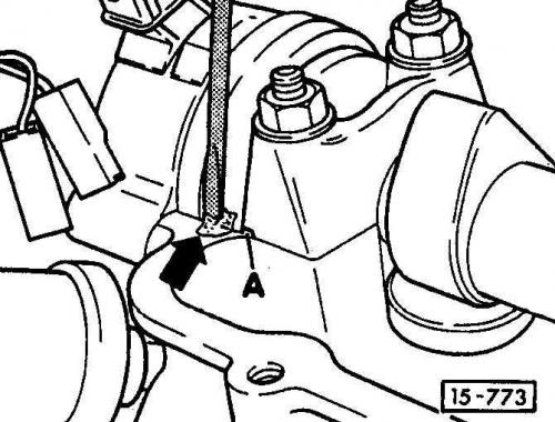
4. Carefully lubricate with grease using a small screwdriver "Silmate AMV 17400401" four edges - arrow - on the contact surface of the cylinder head.
Warning: Do not block the oil hole – A.
5. Before installation, lightly lubricate the contact surfaces of the cylinder head cover gasket with silicone-based anti-slip agent D00700001.
6. Install the cylinder head cover together with the oil level indicator and tighten the bolts evenly to a torque of 10 Nm.
Engines with five valves per cylinder (with a working volume of 2.8 liters (30 valves), 193 hp)
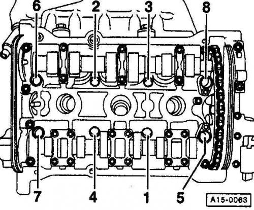
1. The cylinder head bolts are tightened in two stages. In each stage, tighten the bolts in sequence from 1 to 8.
Method 1: using a torque wrench with a torque of 60 Nm.
Method 2: without stopping tightening, turn in the tightening direction by 1/2 turn (180 degrees) using a locked key. It is permissible to perform this technique as 2 tightenings of 90 degrees.
Warning: Further tightening of the cylinder head bolts on a warm engine is not permitted.
2. Screw on the coolant nipple and timing belt cover.
3. Connect the outlet pipe to the outlet branch.
4. Screw the coolant hose onto the rear of the cylinder head.
5. Screw on the CO sampling tube.
6. Install the oxygen sensor.
7. Remove the cloth from the inlet ports.
8. Install the intake manifold with a new sealing gasket. Tighten the bolts in the specified sequence in four stages. The arrow shows the direction of travel of the car.
- Reception 1: 5 Nm;
- Reception 2: 10 Nm;
- Reception 3: 20 Nm;
- Reception 4: 20 Nm.
Warning: For a 2.8L 30-valve engine, tighten the intake manifold to a torque of 10 Nm only.
9. Using a SW 5 Allen key, tighten the cover of the valve injector wires on the left.
10. Insert, install or secure the following wires in accordance with the markings on the tags:
- all spark plug plugs;
- all valve injector plugs;
- idle speed control valve plug on the bottom right side of the intake manifold;
- throttle position sensor plug at the bottom of the throttle valve pipe;
- oil pressure sensor and switch plug at the bottom of the left cylinder head;
- hall sensor plug at the bottom of the left cylinder head;
- oxygen sensor and oxygen sensor heater plug on the end of the cylinder block, near the left cylinder head.
11. Screw the hydraulic line and ground wire bracket to the right side of the intake manifold.
12. Bolt the mechanical EGR valve to the intake manifold.
13. Install the gas rod.
14. Screw on the cover of the valve injector wires on the left.
15. Install the following vacuum lines in accordance with the markings on the tags:
- brake booster vacuum line on the right side of the intake manifold and at the vacuum pump on the right cylinder head;
- vacuum hose on top of the EGR box. The box with the mechanical bypass valve is located on the left at the bottom of the intake manifold;
- vacuum pipeline of the GRA system box (black plastic box). The GRA system switches the intake manifold valve, the box is located next to the EGR system box;
- vacuum line of the throttle valve activated carbon filter tact valve;
- vacuum lines at the intake manifold changeover valve (blue) and at the electric EGR valve (brown). Both valves are located under the air flow meter.
16. Install the muffler at the throttle valve and screw it on. Attach the muffler cover.
17. Connect the following vacuum hoses according to the markings on the tags:
- vacuum hose to the left of the muffler cover;
- hose of the left connecting pipe of the crankcase ventilation system.
18. Install the air hose between the air flow meter and the intake manifold.
19. Screw the crankcase ventilation system to the left and right of the cylinder head.
20. Screw on the fuel supply and outlet pipes.
21. Attach the gas supply line to the mechanical valve of the exhaust gas recirculation system to the outlet pipe (eGR valve).
22. Install the lower engine compartment cover.
23. Connect the negative (-) battery cable. Enter the anti-theft code and program the radio stations.
Warning: The battery may only be connected when the ignition is off, otherwise the injection system control unit will be damaged.
24. Attach the water drain cover and install the rear seat.
25. Fill with coolant. Always renew the coolant.
26. Check the engine oil level. If the cylinder head gasket is defective, replace the oil.
27. Warm up the engine to normal operating temperature, check the coolant level again, and also check the connection points of all hoses for leaks.
Features of the right cylinder head (174hp engines only.)
1. Remove the vacuum pump and plug.
2. Remove the intermediate flange.
3. Remove the piston from the camshaft.
4. Replace O-rings A, B, C and D.
5. Reinstall the piston, intermediate flange and vacuum pump and tighten to 10 Nm.