Install the "T40170" transport protection from below under the gearbox housing and attach it to the shaft with flange "1".

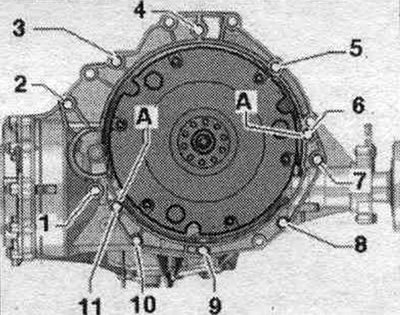
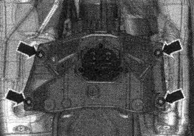
Check the presence of centering bushings "A" for the engine and gearbox in the cylinder block; insert the bushings if necessary. Check the aluminum engine-to-gearbox connection bolts for reuse and, if necessary, mark them. Attach the engine to the gearbox and tighten bolts "6...11" connecting the engine to the gearbox. Remove the "T40170" transport protection.
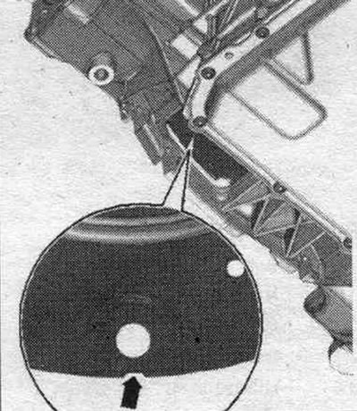
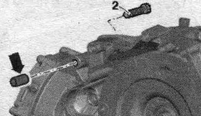
Fix plug "1" in the hole for the starter. The plug "1" must fit tightly "arrows". Depending on the engine, different versions of the plug are provided. If the starter installation is difficult, lightly lubricate the plug. Install the starter.
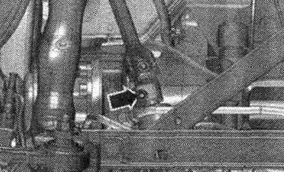
Loosen the lead screws "10-222 A/11". Raise the gearbox and tighten the tunnel crossmember "arrow" bolts. Loosen the harness and remove the lift with the T40173 gearbox mount from under the gearbox.
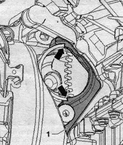
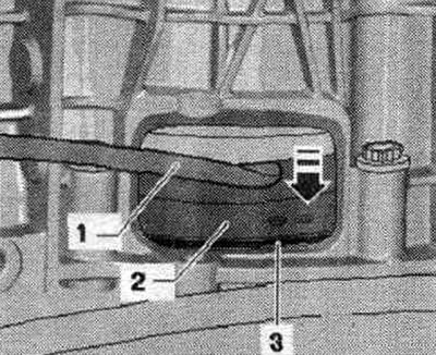
The next stage of work is necessary to ensure uniform contact of the torque converter with the driven disk without distortion. Lightly press the torque converter "2" using the mounting. lever "1" from driven disk "3" in the "direction of the arrow".
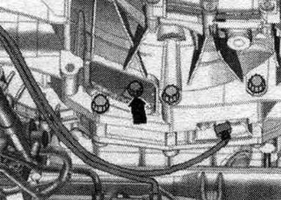
Tighten the torque converter bolts to the driven disc as follows. Use a 16 mm ring spanner to tighten the bolts "VAG 1332/14". Screw in the first "arrow" bolt all the way (2 Nm).
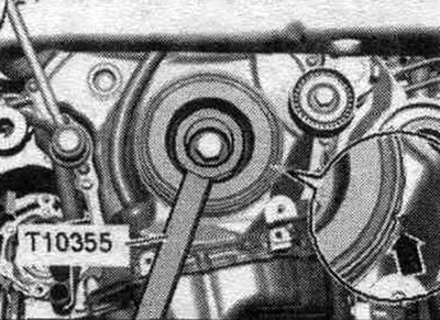
Turn the crankshaft by the torque converter using the counter support "T10355" by 240° in the direction of engine rotation.
With the crankshaft in this position, tighten the accessible bolt "arrow" to a torque of 60 Nm. Rotate the crankshaft 120° and tighten the remaining two bolts to a torque of 60 Nm. Reinstall in reverse order. Tighten the remaining bolts "2...5" connecting the engine to the transmission. Bolt "2" secures the starter to the transmission and is additionally equipped with a spacer sleeve "arrow." The spacer sleeve must be installed between the starter and the transmission. Install the ATF lines. Install the selector cable.
Bolt the steering column to the steering gear. Install the subframe crosspiece. Bolt the left and right drive shafts to the gearbox. Install the PTO shaft heat shield. Install the cardan shaft. Install sys. exhaust gas outlet without mechanical stress and align. Installation of noise insulation. Connect the battery. Check and adjust the selector cable. Check and adjust the ATF oil level.
Tightening torques when installing the gearbox (Nm)
| Bolts and nuts | M6 | 9 |
| M7 | 15 | |
| M8 | 20 | |
| M10 | 40 | |
| M12 | 65 |
Drive shaft heat shield - tightening torque
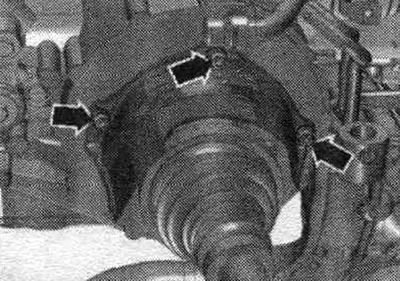
Tighten the drive shaft heat shield arrow bolts to 23 Nm.
Engine mount to gearbox
| Pos. | Bolt | Nm |
| 1 (1) | M10 x 60 (2) | 65 |
| 2 (1), 7 | M12 x 100 (3), (4) | 30 + 90° |
| 3, 6 | M12 x 75 (3), (4) | 30 + 90* |
| 4, 5 | M12 x 120 (3), (4) | 30 + 90° |
| 8, 10 | M10 x75 (3), (4) | 15 + 90° |
| 9 | M10 x 60 (3), (4) | 15 + 90° |
| 11 (5) | M12 x 50 (3), (4) | 30 + 90° |
| A | Centering bushings | |
(1) Additionally secure the starter.
(2) The strength class of bolts is 10.9. The steel bolt can be used repeatedly.
(3) Audi A4 up to ID. numbers 8K-9A-066499: replace aluminum bolts.
(4) Audi A4 with ID. numbers 8K-9A-0665OO: aluminum bolts can be used 2 times.
(5) Fastening the engine to the gearbox.
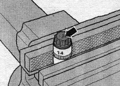
Audi A4 with identification. part numbers 8K-9A-066500: Aluminum bolts "2...11" can be used twice. Therefore, after the first use, mark these bolts with two notches "X" and "arrow" using a cutter. To avoid damaging the bolts during notching, do not clamp them in a vice. Insert the bolt as shown in the illustration into the 14 mm socket using a 1/2-inch drive, which can then be clamped in a vice. Do not reuse bolts marked with "X".