
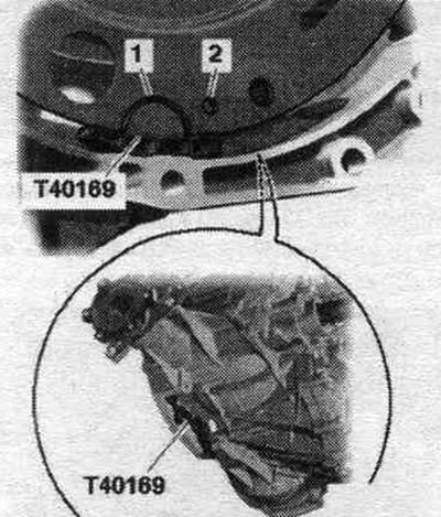
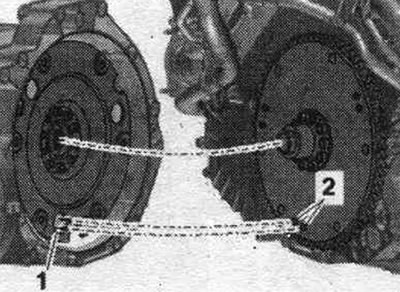
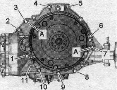
Check the presence of centering bushings "A" for the engine and gearbox in the cylinder block; insert the bushings if necessary. If necessary, check for reuse and mark aluminum bolts "2...11" connecting the engine and transmission. Install the clutch module if necessary. Install the gearbox on the gearbox bracket "T40173" and secure with harness "1", as shown in the figure. Before connecting the engine and gearbox, carry out the following preparatory actions. Insert mont. device "T40169" from below into the gearbox housing and install the clutch module as shown in the figure.
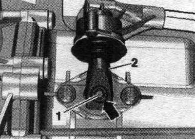
Mounting tool "T40169" should fit into semicircular groove "1" and additionally into inspection hole "2." To locate the inspection hole, it is necessary to rotate the clutch module. Insert mounting bolts. "T40169" device into the hole on the gearbox housing.
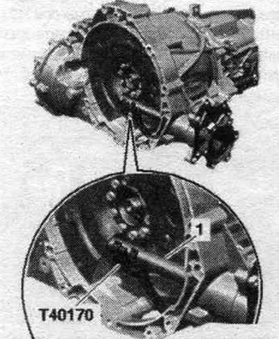
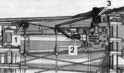
Install the "T40170" transport protection from below under the gearbox housing and attach it to the shaft with flange "1".
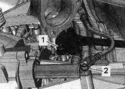
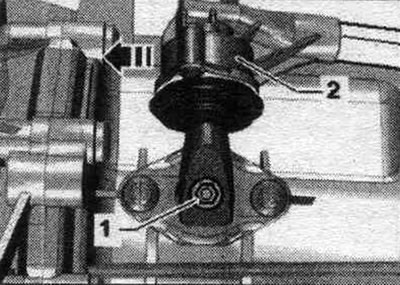
Raise the gearbox so that the clutch slave cylinder can be installed. Tighten bolt "2".
The next step is only necessary if the driven disc with locking pin "2" is installed. Additionally, align the position of the driven disc in relation to the clutch module so that locking pins "2" (if available) on the driven disk could enter the large holes "1" on the clutch module. If the retaining pins of the driven disk "2" do not enter the holes of the clutch module "1", this can lead to serious problems in the operation of the clutch.
Install the gearbox onto the engine and tighten bolts "3...11." Raise the gearbox with a powertrain lift until gap "a" between the tunnel crossmember and the body is reached. Dimension "a" = maximum 100 mm.
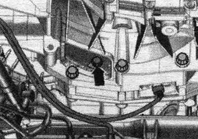
Install the starter and tighten bolts "1" and "4". -Pos. 2...3- do not take into account. Screw on the right catalytic converter.
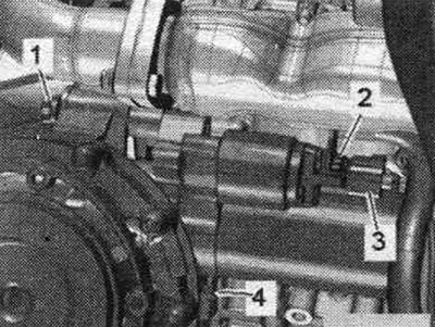
Tighten shift fork rod "1". Tighten connecting rod "3". Connect connector "2" to gear position sensor "F208". Connect connector to engine speed sensor "G28".
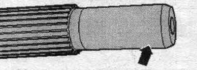
Install gearshift lever "2" as follows: gearshift lever "2" can be installed on shift shaft "1" in only one position (the notch in the gear ring "arrow"). Tighten bolt "2" of the gearshift lever.
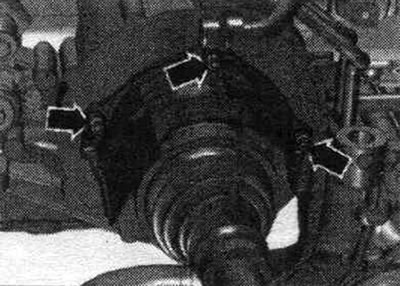
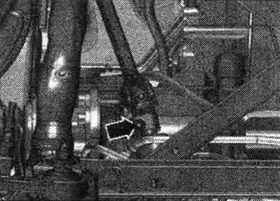
Bolt the right and left drive shafts to the transmission flange shafts. Tighten the drive shaft heat shield "arrow" bolts to 23 Nm.
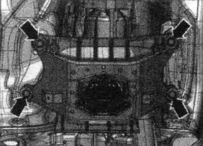
Release the tension on the 10-222 A crossmember lead screw. Continue raising the gearbox and tighten the tunnel crossmember arrow bolts. Remove the tilting device with the "T40173" mounting bracket from under the gearbox. Remove the "10-222 A" crossmember.
Install the propeller shaft on the gearbox. Assemble the system. exhaust and align without tension.
Tightening sequence - clutch module to driven disc
Remove mounting tool "T40169" and transport guard "T40170". Select 6th gear by removing shift shaft "1" and shifting gearshift lever "2" forward in the direction of the arrow.
Set both front. wheels. Secure the driveshaft against rotation using the "T10172" stop and the "T10172/5" adapter. This next step is essential to ensure uniform contact with the driven disk without distortion. Rotate both fronts. wheels in one direction so that the clutch module makes 1 full revolution. The inspection hole "arrow" should be visible again in the recess of the gearbox housing.
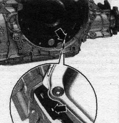
Tighten the clutch module bolts to the driven disc as follows: use only new bolts. Tighten the bolts with a 16 mm ring spanner "VAG 1332/14". Tighten the first bolt "arrow" by hand (2 Nm). Tighten the clutch module/flywheel disc further at both front. wheels by 180°. Now screw in the 2nd bolt and tighten to the specified torque. Now screw in the remaining bolts securing the clutch module to the driven disk one by one and tighten immediately (even a bolt that has just been screwed in) moment.
Screw the cardan joint "arrow" to the steering gear.
Install power steering lines. Install the subframe crosspiece. Fill the hydraulic fluid. Check the manual transmission fluid level. Tighten the front wheels to the specified torque. Pay attention to the battery replacement work.
Tightening torques (Nm)
| Bolts and nuts | M6 | 9 |
| M7 | 15 | |
| M8 | 20 | |
| M10 | 40 | |
| M12 | 65 |
Manual transmission mount for 3.0L TFSI engine
| Pos. | Bolt | Nm |
| 1 (1) | M10 x 50 (2) | 65 |
| 2 (1) | M12 x 100 (3), (4) | 30 + 90° |
| 3...6 | M12 x 100(3), (4) | 30 + 90° |
| 7 | M12 x 125 (3), (4) | 30 + 90° |
| 8, 11 | M10 x 60 (3), (4) | 15 + 90° |
| 9, 10 | M10 x 95 (3), (4) | 15 + 90 |
| A | Centering bushings | |
(1) Additionally secures the starter.
(2) Bolt strength 10.9; this steel bolt can be used repeatedly.
(3) Audi A4 up to ID. numbers 8K-9-066499: replace aluminum bolts.
(4) Audi A4 with ID. part numbers 8K-9-066500: Aluminum bolts can be used twice. Check aluminum bolts "2...11" for reinstallation.