
Table of contents: Fusible links ↓ Relay ↓
1. The main fuses and relays are located under the cover on the front panel on the right side.
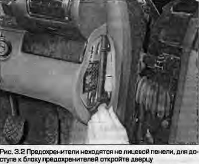
2. To access the fuses, open the cover on the front panel (Fig. 3.2).
3. The circuits protected by the fuses and relays are marked on the inside of the cover. The fuses are numbered. A list of the circuits protected by the fuses is given at the end of this chapter.
4. In some models, there are additional fuses installed in separate blocks behind the relay.
5. To remove a fuse, first make sure the ignition is off or the circuit in question is disconnected. Open the cover and pull the fuse out of the socket using the provided claw. The burnt conductor is usually visible through the transparent fuse housing.
6. Always use new fuses of the specified rating. Never use fuses of a higher rating than specified, do not install temporary "bugs" in the form of paper clips, foil, etc. This leads to more serious damage, or even a fire. The fuse rating is printed on its body. Please note that fuses are painted in different colors according to the rating.
7. If a newly installed fuse blows immediately, do not install the next one until you find out the cause - most often the cause is a short circuit in the target (to "ground"). If the fuse protects several circuits, disconnect them all and connect them one by one until the fuse blows again - this will make it easier to find the fault. Always install fuses of the prescribed rating. Spare fuses should be attached to the base of the fuse box.
Fusible links
8. On diesel models, the spark plug supply circuit is protected by a fusible link - a powerful fuse. The link is located under a protective plastic cover at the rear of the engine compartment, behind the heater inlet deflector. A burnt link indicates serious damage to the target or a shorted spark plug - do not replace the link until the cause is determined.
9. Before replacing the insert, disconnect the ground wire from the battery. Open the cover to gain access to the insert. Loosen the mounting screws and remove the insert.
10. Install the new insert (see information in paragraphs 6 and 7) and tighten the mounting screws securely. Snap the cover into place.
Relay
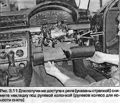
11.. The relays are mounted on a common block, which can be accessed by removing the cover under the steering column (Fig. 3.11).
12. The relay is a non-separable structure, its repair is not provided. To replace the relay from the socket, it must be removed. In some cases, to do this, press outward two latches.
13. If a fault occurs in a circuit or system controlled by a relay and there is a suspicion of a faulty relay, turn on the system. If the relay is functioning, clicks should be heard, indicating that power is being supplied to the relay. If there are clicks, this indicates either a faulty actuator circuit or a faulty actuator contacts of the relay. If there are no clicks, then either the relay is faulty or it is not receiving power from the control circuit. To find the cause, replace the relay with a known good one, but be careful - many relays look the same externally, but perform different functions.
14. Before replacing the relay, turn off the ignition. Remove the faulty relay and insert a new, working one.
Note: The turn signal/hazard warning relay is built into the hazard warning switch; the removal procedure is described in paragraph 6.