
Table of contents: Switches on the front panel ↓ Polite Lighting Switches ↓ Side mirror adjustment switch ↓ Electric sunroof control switch ↓ Handbrake indicator switch ↓ Door mounted power window switches ↓ Brake light switch/sensor ↓ Steering column switches ↓
Switches on the front panel
1. Using a small screwdriver, carefully pry the switch out of the front panel. Place a piece of cardboard or rag under the screwdriver to avoid scratching the front panel.
2. Remove the switch housing from the console with long-nose pliers and disconnect the connector from the back of the switch.
3. Installation - reverse procedure.
Polite Lighting Switches
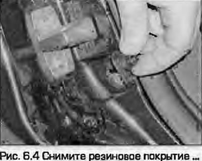
4. Remove the rubber covering (Fig. 6.4).
5. Remove the Phillips head screw.
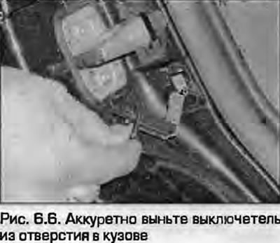
6. Carefully remove the switch from the hole in the body (Fig. 6.6). Disconnect the wiring and remove the switch. Do not let the wiring fall inside the pillar - tape it with tape.
7. Installation - reverse procedure.
Side mirror adjustment switch
8. Remove the door trim panel and water-resistant membrane - see chapter 11.
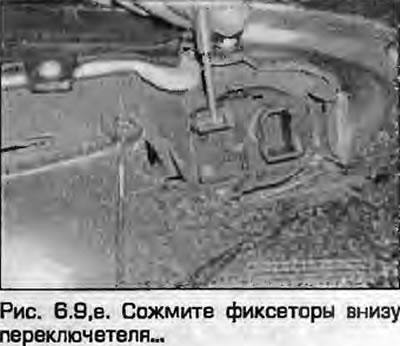
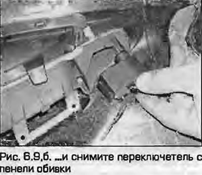
9. Disconnect the connector. Squeeze the tabs at the bottom of the switch and remove the switch from the trim panel (Fig. 6.9).
 |
 |
10. Installation - reverse procedure.
Electric sunroof control switch
11. Using a small screwdriver, remove the switch/light panel from the roof panel.
12. Disconnect the connector from the switch.
13. Remove the handle from the switch shaft, unscrew the mounting nut and remove the switch from the roof panel.
14. Installation - reverse procedure.
Handbrake indicator switch
15. Remove the rear section of the center console as described in chapter 11.
16. Loosen the screw and remove the switch from the lever. On some models, the switch is simply secured with a latch on the mounting bracket.
17. Disconnect the wiring from the switch.
18. Installation - reverse procedure.
Door mounted power window switches
19. Remove the door trim panel and water-deflecting membrane as described in chapter 11.
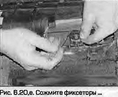
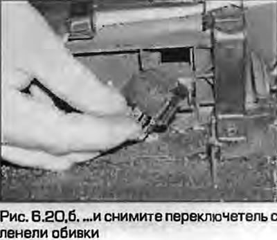
20. Squeeze the clips and remove the switch from the trim panel (fig. 6.20, a, b).
 |
 |
21. Installation - reverse procedure.
Brake light switch/sensor
22. Refer to the description chapters 9.
Steering column switches
23. Refer to the description paragraph 5.
(The original source of the article can be found on the website: AudiManual)